
© 2023 Created by blog.championxperience.com
What is GD&T?
Geometric Dimensioning and Tolerancing (GD&T) is a symbolic language used on engineering drawings to control the shape, size, orientation, and location of features.
Understanding how to apply GD&T symbols in engineering drawings ensures proper fit, function, and interchangeability of parts throughout manufacturing and assembly.

Datums in GD&T
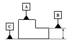
A datum is a theoretical reference (plane, line, or point) used for measurement.
Common datum symbols:
A, B, C (primary, secondary, tertiary)
 Application:
- Datum A → base surface
- Datum B → side face
- Datum C → hole or edge
Type of GD&T Symbols

Form Controls
Form controls are used to control the shape of a feature, independent of its size, location, or orientation.
Unlike other GD&T controls, they do not require a datum reference.
These controls focus purely on the geometry of individual features.
In GD&T, form controls are classified into four types:
Straightness:
Straightness specifies that a line element of a feature, or the axis of a feature of size, must lie within a straight tolerance zone defined by two parallel lines (or a cylindrical zone for an axis).
- It controls only shape, not orientation or location.
The tolerance zone is:
Two parallel lines (for surface elements)
A cylinder (for an axis or centerline)
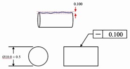
Two types of straightness:
- Surface straightness:
Controls straightness of individual line elements on a surface.
Tolerance zone: two parallel lines.
- Axis straightness:
Controls straightness of the derived axis of a shaft or hole.
Tolerance zone: a cylindrical
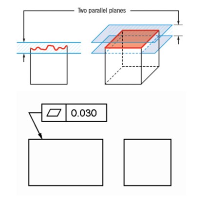
Flatness:
Flatness is a form tolerance that controls how much a surface can deviate from a perfectly flat plane.
- Flatness is a form control.
- No datum reference is allowed.
- It controls only surface shape, not orientation or location.
The tolerance zone is two parallel planes.
For example, when a surface has a flatness tolerance of 0.05 mm, then the entire surface must, therefore, lie between two parallel planes spaced 0.05 mm apart.
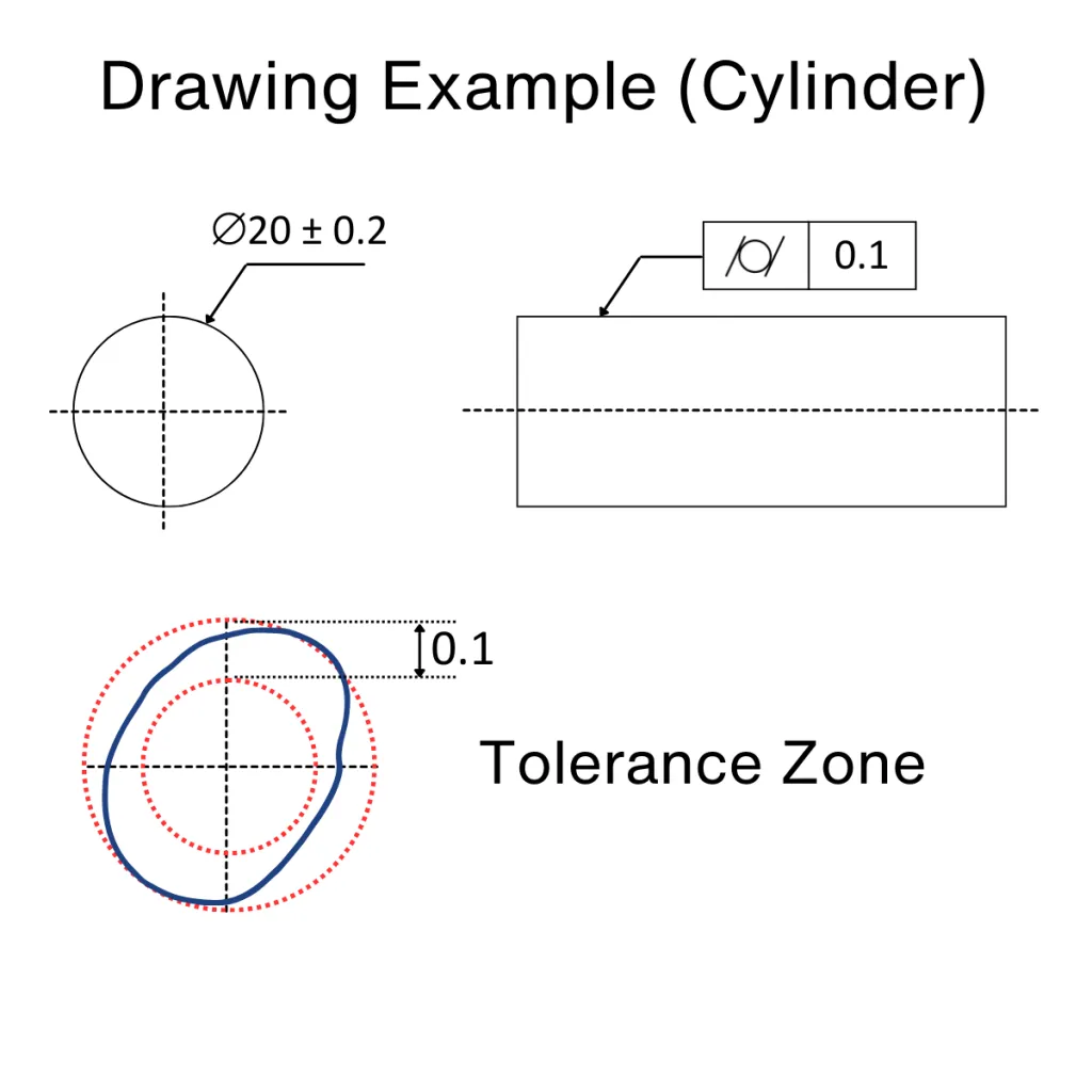
Circularity:
Circularity specifies that each circular cross-section of a feature must lie within a tolerance zone defined by two concentric circles, separated by the tolerance value.
- Circularity is a form control.
- No datum reference is required.
- It controls only the shape, not size, orientation, or location.
The tolerance applies to every circular element along the feature.
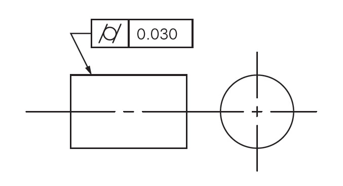
For example: If a shaft has a circularity tolerance of 0.01 mm, every circular cross-section of the shaft must fit between two concentric circles 0.01 mm apart.
Cylindricity:
Cylindricity specifies that the entire surface of a cylinder must lie within a tolerance zone defined by two concentric cylinders, separated by the tolerance value.
- Cylindricity is a form control.
- No datum reference is allowed.
- It controls roundness, straightness, and taper simultaneously.
The tolerance applies to the entire cylindrical surface, not individual cross-sections.
For example: If a shaft has a cylindricity tolerance of 0.02 mm, the whole cylindrical surface must fit between two concentric cylinders 0.02 mm apart.
Applications:
- Ensuring flat sealing surfaces
- Maintaining straight shafts
- Controlling round holes and pins
- Maintaining proper fit in rotating parts.
Orientation Controls
Orientation controls define the angular relationship—such as tilt or direction—of a feature relative to a datum reference.
t=”258″ data-end=”261″ />>Orientation controls align features correctly to support proper function and assembly.
Designers must always specify a datum reference when applying orientation controls.
In GD&T, orientation controls are classified into three types:
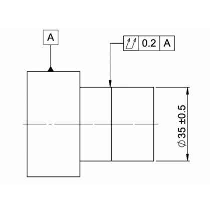
Angularity :
Angularity specifies that a surface, axis, or center plane must be oriented at a specified angle (other than 0° or 90°) relative to a datum reference, within a defined tolerance zone.
Surface angularity: Two parallel planes at the specified angle.
Axis angularity: A cylindrical tolerance zone at the specified angle.
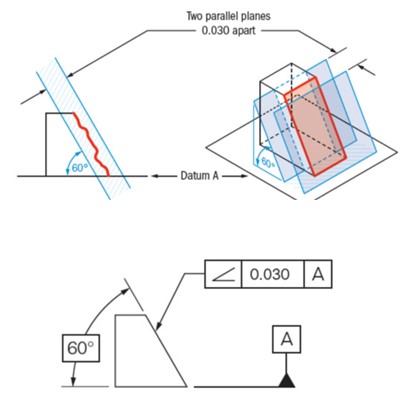
For example: If a surface has an angularity tolerance of 0.05 mm at 30° relative to datum A, the surface must lie between two parallel planes 0.05 mm apart, oriented 30° to datum A.
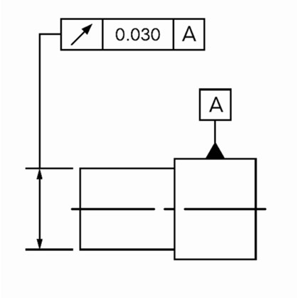
Perpendicularity:
Perpendicularity specifies that a surface, axis, or center plane must be oriented at 90° to a datum reference, within a specified tolerance zone.
Surface perpendicularity: Two parallel planes perpendicular to the datum.
Axis perpendicularity: A cylindrical tolerance zone perpendicular to the datum.

For example: If a hole has a perpendicularity tolerance of 0.02 mm relative to datum A, the axis of the hole must lie within a 0.02 mm diameter cylindrical zone that is perpendicular to datum A.
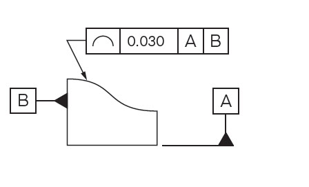
Parallelism:
Parallelism specifies that a surface, axis, or center plane must be oriented parallel to a datum reference, within a specified tolerance zone.
Surface parallelism: Two parallel planes parallel to the datum.
Axis parallelism: A cylindrical tolerance zone parallel to the datum.
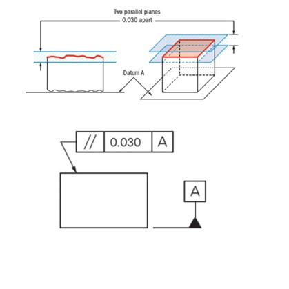
For example: If a surface has a parallelism tolerance of 0.03 mm relative to datum A, the surface must lie between two parallel planes 0.03 mm apart, oriented parallel to datum A.
Applications:
- Perpendicular drilled holes
- Parallel sliding surfaces
- Angled mounting faces
- Machined components
Location Controls:
Location controls used to control the exact position of a feature relative to one or more datum references.
- Datum required.
Position:
Position defines the allowable variation for the axis, center point, or center plane of a feature of size.
The tolerance zone is located and oriented using datum references relative to the feature’s true position.
This control ensures accurate placement of features for proper assembly and function.
In GD&T, position is classified as a location control.
- Datum references are required.
- It controls location and orientation, but not size.
- It is the most widely used GD&T tolerance.
Can be applied with MMC, LMC, or RFS material conditions.

For example: If a hole has a position tolerance of ⌀0.10 mm relative to datums A, B, and C, the axis of the hole must lie within a 0.10 mm diameter cylindrical tolerance zone located from the true position defined by those datums.
Applications:
- Bolt hole patterns.
- Shaft and hub alignment.
- Assembly fit and interchangeability.
- Precision mechanical parts.
Profile Controls
Profile controls define the allowable variation of a line or a surface from its true geometric profile.
Depending on the design requirement, datum references may or may not be used.
These controls are commonly applied to complex shapes where form and location must be controlled together.
Profile of a surface:
This control requires all points on a surface to lie within a tolerance zone.
The zone is bounded by two offset surfaces that are equally disposed about the true profile.
The true profile itself is defined directly by the drawing.
- It controls size, shape, orientation, and location of a surface simultaneously.
- Can be applied to flat, curved, or complex surfaces.
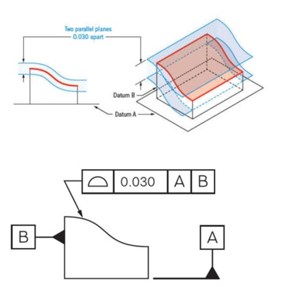
For example:-If a curved surface has a profile of surface tolerance of 0.5 mm relative to datums A and B, the entire actual surface must lie within ±0.25 mm of the true profile, oriented and located from those datums.
Profile of a line:
Profile of a line specifies that each line element of a surface, taken in a specified direction, must lie within a tolerance zone bounded by two parallel lines, equally disposed about the true profile.
- It applies to individual 2D cross-sections, not the entire surface.
- Used for curves, angles, and irregular shapes
For example:
When a designer applies a 0.2 mm profile of a line tolerance to a cam profile, each specified cross-section of the cam must lie within ±0.1 mm of the true profile.
Applications:
- Turbine blades
- Plastic molded parts
- Aerodynamic surfaces
Runout Controls
Runout controls define the allowable variation of a surface when rotated about a specified datum axis.
- Control variation during rotation.
- Datum required.
Circular runout:
Circular runout requires each circular cross-section of a rotating feature to remain within the specified tolerance zone as the part rotates 360° about the datum axis.
- Inspectors measure circular runout using a dial indicator while rotating the part.
- This control applies to individual circular elements rather than the entire surface.
For example: If a shaft has a circular runout tolerance of 0.03 mm relative to datum A, then at any given cross-section, the total indicator reading (TIR) must not exceed 0.03 mm during one full rotation.
Total runout:
Total runout specifies that the entire surface of a rotating feature must remain within a tolerance zone as the part rotates 360° about the datum axis.
- It controls the entire surface, not individual cross-sections.
- Measured by sweeping a dial indicator along the full length of the feature during rotation.
For example, if a shaft has a total runout tolerance of 0.04 mm relative to datum A, then the maximum indicator variation over the entire length and throughout a full rotation must not exceed 0.04 mm.
Applications:
- Rotating shafts
- Brake discs
- Motor components
Key Takeaways
When engineers apply GD&T thoughtfully, it helps everyone from design to manufacturing and inspection, understand the design in the same way. Knowing how to apply GD&T symbols in engineering drawings reduces confusion, avoids unnecessary rework, and supports smoother collaboration across teams. In the end, GD&T is not just about symbols on a drawing; it’s about making sure the part works as intended in the real world.

Design Engineer at Zeeta Electricals
Mahesh is a Mechanical Design Engineer with a B.Tech in Mechanical Engineering and currently works at Zeeta Electricals. He is a design enthusiast with a strong interest in mechanical engineering and product design. Highly motivated to continuously develop his skills, he is passionate about creating efficient and practical engineering solutions. His technical expertise includes CATIA V5, SOLIDWORKS, AutoCAD, Creo, and sheet metal design, and he is always eager to grow professionally while contributing value to his organization.
Latest posts by Mahesh Singh (see all)
- How to apply GD&T symbols in engineering drawings - 21 December 2025

[…] MBD brings GD&T, communication, and manufacturing workflows together in a single cloud-native environment. […]