

Have you ever opened a beautifully detailed CAD assembly, ready to run a high-fidelity CFD simulation, only to watch your meshing algorithm choke on a tiny, forgotten logo stamp or a microscopic sliver face? If you are a simulation analyst or a mechanical designer, you know this pain all too well. You end up spending days manually cleaning up geometry, stripping out chamfers, and patching tiny gaps instead of doing what you actually love: analyzing physics and optimizing designs.

The transition from CAD to CAE has historically been the single biggest bottleneck in the simulation pipeline, often eating up to 50% of an engineering project’s budget. But it does not have to be this way. Let’s look at how a dedicated simulation geometry preprocessor can bridge this gap and turn a frustrating multi-day chore into an automated, hour-long breeze.
We have all been there. The design team hands over a massive, production-ready assembly. On paper, it is a masterpiece. But to a meshing engine, it is a minefield of non-manifold topologies, overlapping surfaces, and unlinked structural cutouts. If you try to mesh it as-is, you end up with a bloated mesh, poor cell quality, and a solver that refuses to converge.
Traditionally, engineers had to send the model back to the CAD team or spend hours manually remodeling the fluid domain. This back-and-forth destroys project momentum. To build a watertight computational domain efficiently, we need tools designed specifically for the analyst’s workflow, not the manufacturer’s drawing board.
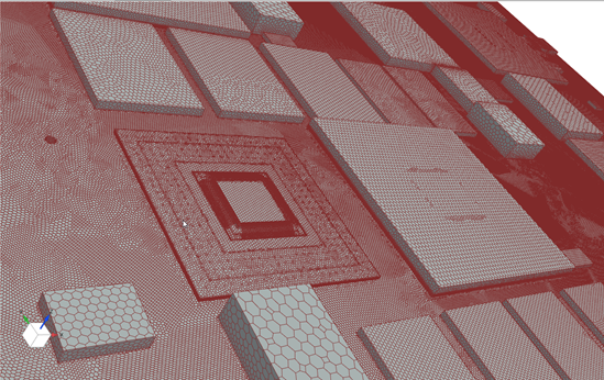
Standard CAD systems are built to define physical parts for manufacturing. They excel at capturing every thread, chamfer, and corporate logo. However, simulation requires the exact opposite: a simplified representation that captures the core physics without the computational overhead.
This is where a dedicated geometry preprocessor comes in. Rather than replacing your CAD system, it acts as a translator. It takes complex B-Rep data and refines it into a clean, simulation-ready format while keeping the underlying design intent fully intact.
A great simulation preprocessor must do more than just view files. According to the Siemens Simcenter team, an effective geometry preprocessor relies on five core pillars:
Siemens has built an incredibly tight pipeline that connects NX CAD, Teamcenter PLM, and Simcenter STAR-CCM+. By using PLMXML schemas and the NX Adaptor, you can pull structured assets directly into your simulation environment. This maintains 100% data provenance, keeping your assembly hierarchies and metadata completely intact without manual export data loss.
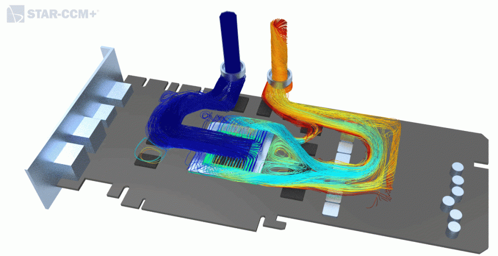
Once your model is inside the Simcenter STAR-CCM+ geometry preprocessor, you can unleash a suite of advanced repair and defeaturing tools:
If you need to make localized adjustments, you do not have to beg the CAD team for a redesign. The built-in freeform modeling engine allows you to perform direct surface morphing and aerodynamic optimization loops right on the simulation canvas.
Design is an iterative journey. When the CAD team releases a new revision, you should not have to rebuild your simulation from scratch. Thanks to the Model Reimport feature in Simcenter STAR-CCM+, you can right-click your ImportCad feature node, select the updated file, and let the software automatically map your existing operations to the new geometry, as highlighted by Volupe’s technical guide.
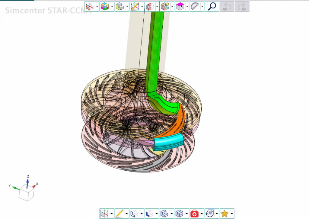
Additionally, handling massive assemblies with thousands of repetitive parts can easily trigger a memory bottleneck. Recent software updates address this by utilizing pre-existing CAD instance information. This means any repair or modification you apply to one body automatically propagates to all identical instances, dramatically lowering memory consumption and keeping your models lightweight.
For those running cutting-edge simulations, the performance gains are scaling rapidly. In fact, the latest Simcenter STAR-CCM+ 2510 release features a new Parallel Surface Wrapper that is up to 82% faster, alongside a discrete proximity checker that runs 30x to 100x faster than legacy CAD-based methods.
Let’s look at how a modern, integrated PLM-to-CAE workflow stacks up against the old-school manual export method:
| Workflow Aspect | Traditional Manual Export | Integrated Simcenter Workflow |
| Data Integrity | Neutral files (IGES/STEP) strip metadata and hierarchy. | PLMXML preserves 100% assembly structure and metadata. |
| Defeaturing & Cleanup | Manual remodeling in CAD; takes days. | Automated defeaturing and patching; takes hours. |
| Design Iterations | Starting the cleanup and meshing process over from scratch. | SeamlessModel Reimportpreserves downstream simulation setups. |
| Memory Management | Unmanaged duplicate components slow down the system. | Smart object instancing keeps files lightweight and fast. |
By removing the friction between design and analysis, engineering teams can shift their focus from fixing broken CAD faces to exploring deeper design spaces. Are you ready to stop fighting your CAD geometry and start simulating faster? Let us know in the comments how much time your team spends on geometry cleanup, and don’t forget to subscribe for our next deep dive into automated meshing workflows!
This guide is based on insights from the official Siemens Blog



[…] This guide is based on insights from the official Siemens Blog. […]