Have you ever spent hours waiting for an electromagnetic simulation to finish, only to realize that most of your solver’s computational power was wasted on meshing the empty air surrounding your model? If you design power electronics for electric vehicles (EVs), you know this frustration all too well. As we push for higher power densities and faster switching frequencies, managing parasitic effects like voltage ringing and electromagnetic interference (EMI) becomes a daily battle.
Fortunately, the release of Simcenter Flux 2026.1 brings a massive breakthrough for simulation engineers. By combining the Partial Element Equivalent Circuit (PEEC) integral method with Surface Impedance Boundary Conditions (SIBC), Siemens has unlocked a staggering 15x speedup in parasitic extraction . Let’s dive into how this workflow functions and how you can apply it to your next design.
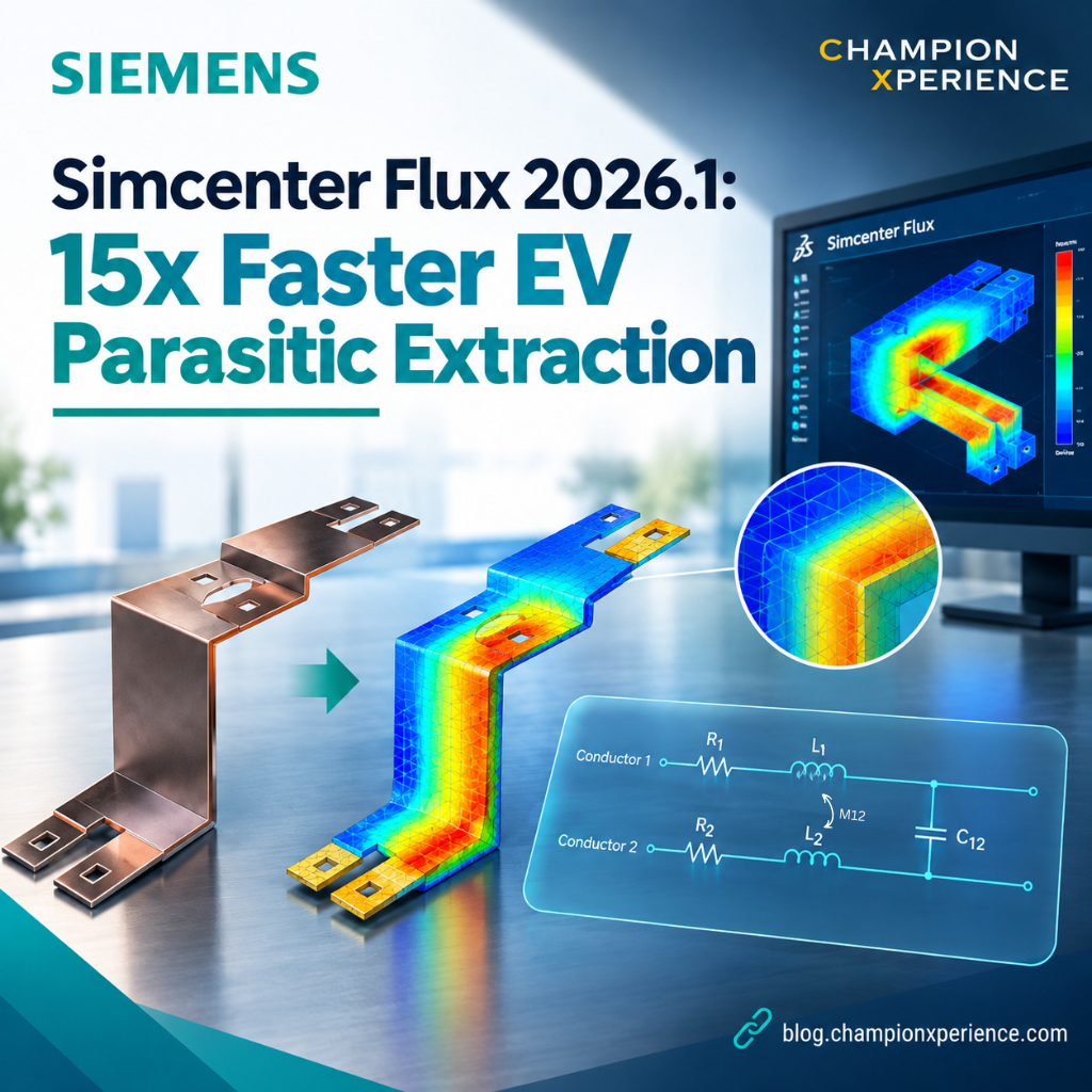
To make electric drivetrains more efficient, powertrain designers are turning to wide-bandgap semiconductors like Silicon Carbide (SiC) and Gallium Nitride (GaN). These materials allow inverters to switch at much higher frequencies—often ranging from 10 kHz to well over 100 kHz .
While faster switching reduces energy losses and allows for smaller passive components, it introduces a major physical headache: parasitic inductance, capacitance, and resistance. At high frequencies, even a tiny amount of unintended inductance in a laminated busbar can trigger severe voltage overshoots, ringing, and EMI issues that threaten to destroy sensitive semiconductor gates.
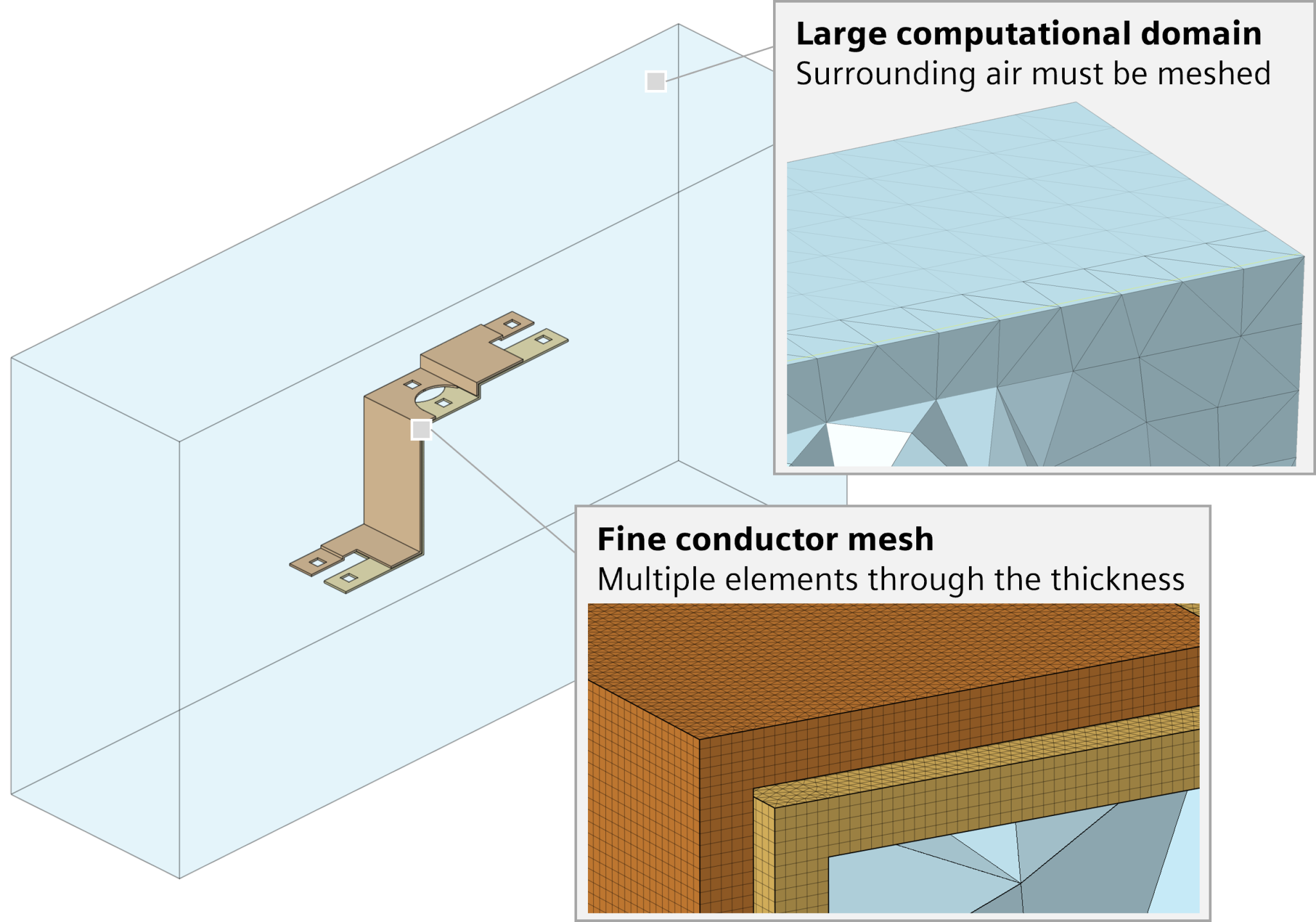
For decades, the Finite Element Method (FEM) has been the gold standard for low-frequency electromagnetic simulation. It works beautifully for electric motors where the fields are tightly self-contained. But when you try to apply traditional FEM to planar components like busbars, the workflow slows to a crawl.
There are two main reasons for this bottleneck:
To bypass the air-meshing trap, Simcenter Flux leverages the Partial Element Equivalent Circuit (PEEC) method . Because PEEC is an integral formulation, it only requires you to mesh the active physical parts of your model—the conductors, dielectrics, and magnetic materials .
By completely eliminating the need to discretize the surrounding air, your solver focuses 100% of its mathematical effort on the components that actually drive parasitic behavior. This makes PEEC incredibly efficient for thin, sprawling geometries like laminated busbars and power module interconnects.
Additionally, the broader Simcenter Flux 2026.1 release expands these capabilities by extending the Volume Integral Method to transient magnetic simulations, offering non-conforming mesh support that gives you even more flexibility during model setup .
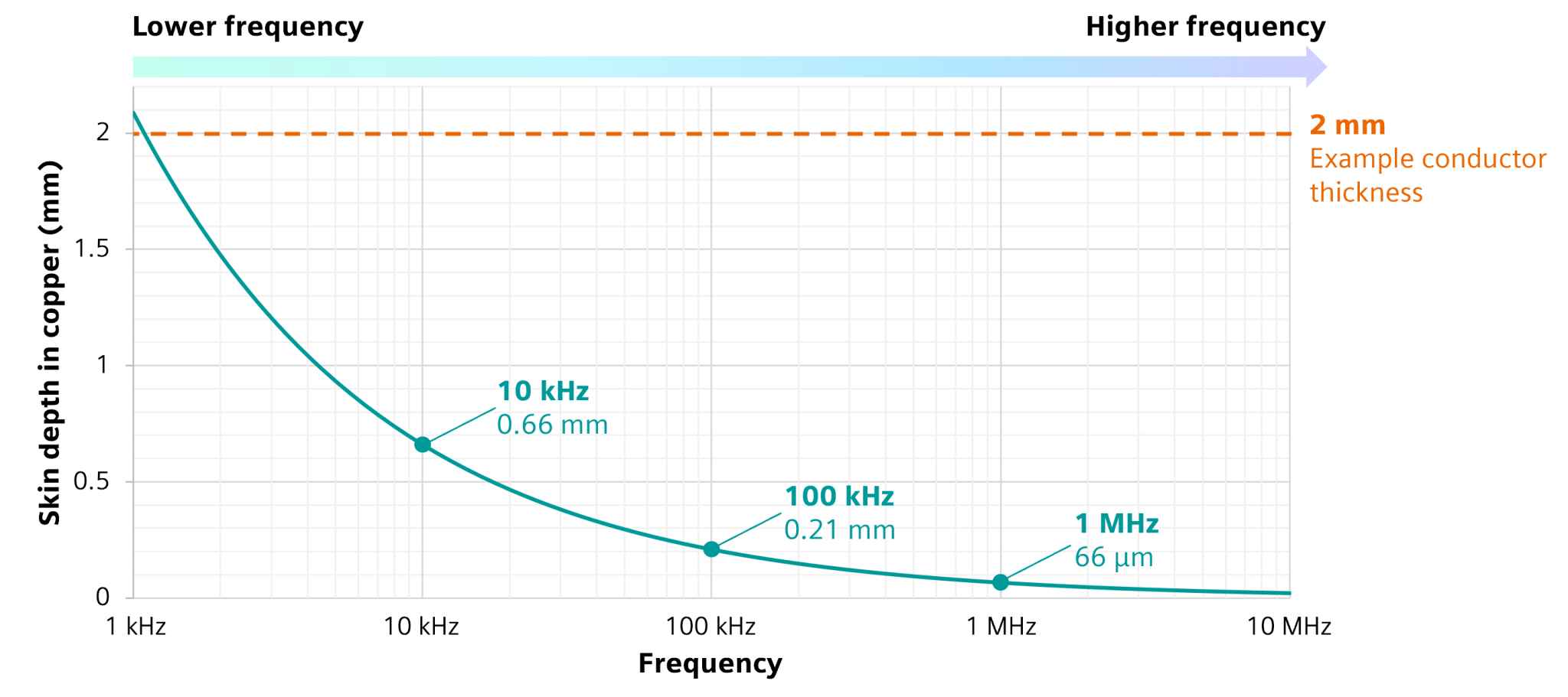
While PEEC solves the air-mesh problem, we still have to deal with the skin effect at high frequencies. This is where Surface Impedance Boundary Conditions (SIBC) come into play.
Instead of forcing you to build a dense, multi-layered 3D volume mesh through the thickness of a thin conductor, SIBC mathematically represents high-frequency electromagnetic behavior directly on the conductor’s surface . This allows you to use a single, highly optimized mesh layer through the thickness of the conductor while still perfectly capturing the frequency-dependent resistance and inductance .
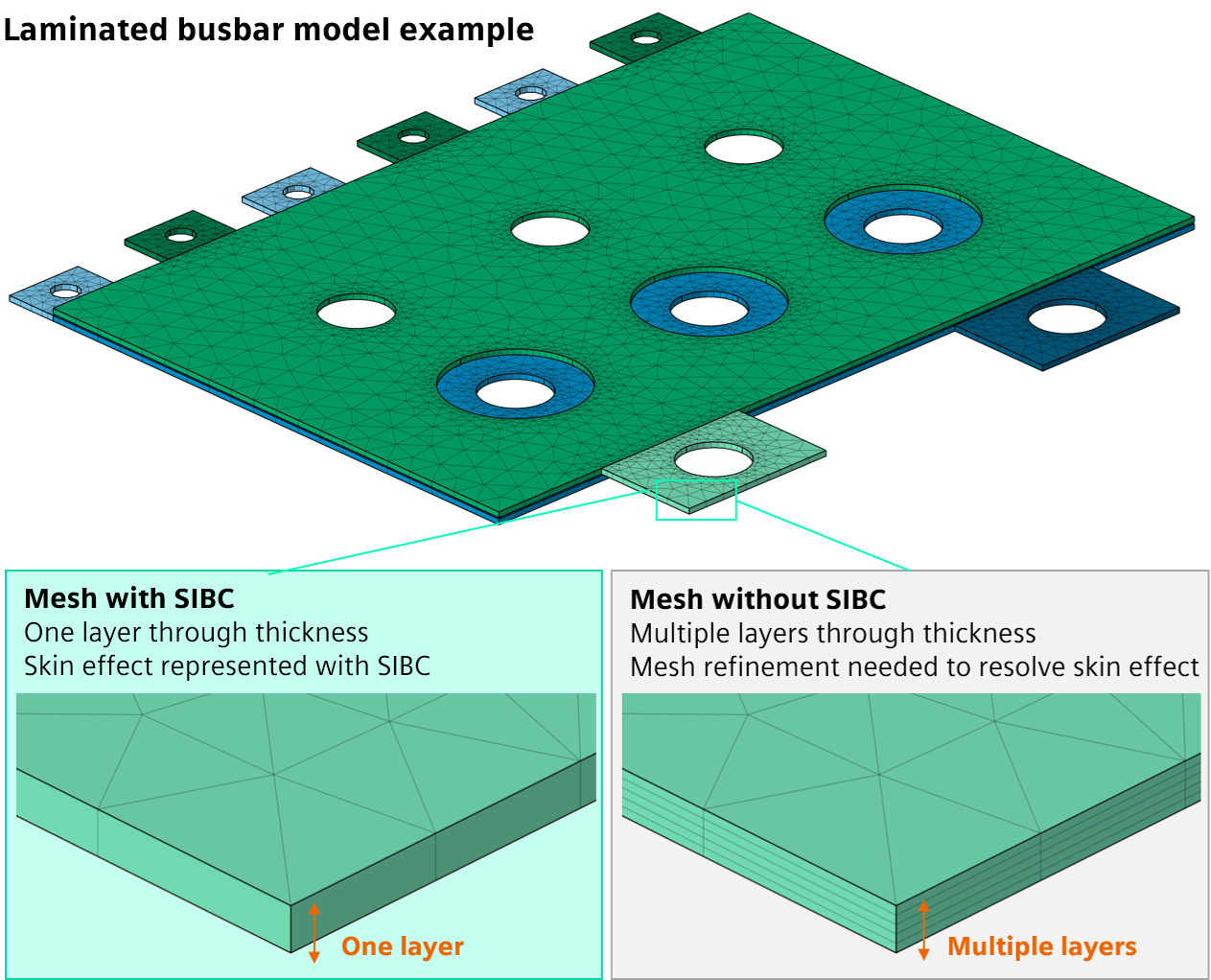
To put this into perspective, let’s look at how these two approaches compare when analyzing a typical laminated busbar. The performance difference is night and day:
| Metric | Without SIBC (Standard Volume Mesh) | With SIBC (Simcenter Flux 2026.1) |
| Five layers through each busbar conductor | One single layer through each busbar conductor | |
| 30 minutes | 2 minutes (15x speedup!) | |
| Resistance significantly underestimated at high frequencies unless mesh is excessively refined | Skin effect captured accurately through the surface impedance formulation | |
| Extremely dense refinement required to resolve skin depth | Standard, geometry-optimized mesh |
Siemens has tightly integrated this advanced solver technology into the unified Simcenter Simlab environment . Here is how you can set up a parasitic extraction run from scratch:
Start by importing your native 3D CAD geometry of the laminated busbar directly into Simcenter Simlab . The software preserves the physical arrangement of your conductive sheets, insulation layers, and terminals.
Using the EM Mesh tool, apply mesh controls to the connection faces and generate an extruded mesh made of wedge elements . Remember, because we are using an integral method, you do not need to create an air box or mesh any surrounding empty space .
Set up a Parasitic Extraction (PE) solution within Simcenter Simlab . Define your frequency sweep to cover your inverter’s operating spectrum, assign electrical ports to your terminals, and apply material properties from the built-in library .
Navigate to the solver settings in Simcenter Simlab and enable SIBC . The Simcenter Flux solver will now automatically apply the surface impedance formulation to handle the high-frequency skin effect .
Run the solver. Within minutes, you can plot your frequency-dependent resistance, R(f), and inductance, L(f) . These curves will clearly show you where proximity and skin effects begin to dominate your design.
Accelerating your simulations from half an hour down to two minutes does more than just save time—it fundamentally changes how you design. Instead of running a single validation check at the end of your project, you can now use simulation as an active design tool.
With rapid feedback, you can easily iterate on conductor placement, optimize busbar geometry to minimize loop inductance, and mitigate EMI risks long before you ever order a physical prototype. It bridges the gap between early-stage CAD layout and high-fidelity virtual validation.
Are you ready to see how much time you can shave off your electromagnetic design cycles? How will a 15x speedup change your team’s development timeline for next-generation EV powertrains?
This guide is based on insights from the official Siemens Blog.