
© 2023 Created by blog.championxperience.com
Introduction
During my internship at AEM, a Moroccan company specializing in mechanical manufacturing for the food industry, I had the opportunity to take part in a project that perfectly combined design precision, digital simulation, and hands-on machining the production of a multi-cavity mold using Mastercam.

This project was more than a technical challenge; it was a complete learning journey that bridged classroom theory and real-world application. Through it, I learned how digital manufacturing software supports every step of the machining process — from planning and toolpath generation to simulation and physical production.
Understanding the Project
The objective was to design and machine a multi-cavity mold used in food-processing equipment. Such molds demand exceptional precision, repeatability, and surface finish to ensure consistent product quality during mass production. Even the smallest dimensional variation could affect the fit and function of the final product, making accuracy absolutely critical.
Before any machining work began, I started by analyzing the 3D CAD model to understand the design intent, geometric tolerances, and surface requirements. This stage helped define how the mold would be manufactured, including the tool types, machining order, and finishing processes needed.
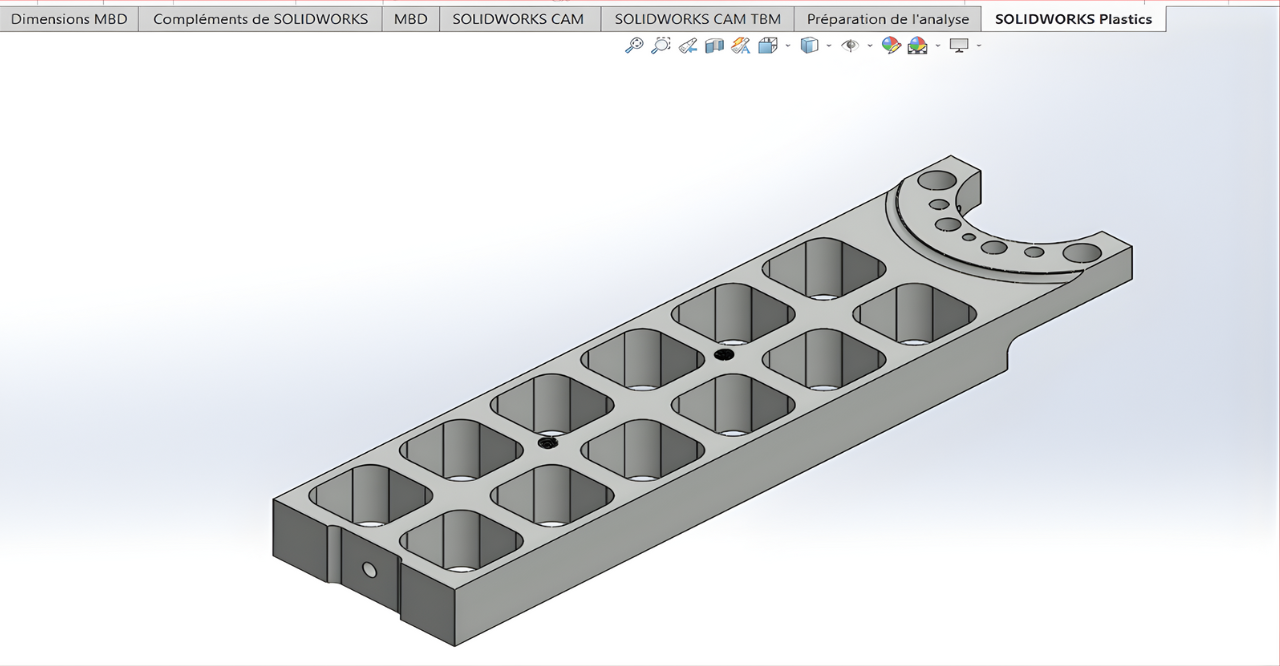 Figure 1: 3D model of the multi-cavity mold
Setting Up the Workflow in Mastercam
Once the design was analyzed, I imported the CAD model into Mastercam to prepare the machining strategy. The first tasks involved defining the stock size, establishing the work coordinate system (WCS), and planning an efficient workflow to balance machining time and precision.
MasterCam’s flexibility allowed me to quickly create a sequence of operations, including roughing, semi-finishing, and finishing passes. Each stage was carefully simulated to visualize tool movement and ensure there were no collisions or wasted tool travel.
One of the most powerful features I used was Dynamic Motion technology. It optimizes tool engagement with the material, reducing heat buildup and extending tool life while maintaining a steady chip load. Using this feature, I could fine-tune the feed rates and cutting parameters to achieve maximum efficiency.
The simulation environment became an invaluable step in the process. It provided a virtual test run of the entire machining sequence, which helped identify potential errors and allowed me to make data-driven adjustments before generating the G-code.

Figure 2: MasterCam toolpath simulation
Machining Process at AEM
After verifying all toolpaths, I transferred the G-code to the CNC milling machine in AEM’s workshop. The machining phase was divided into several key stages, each with specific goals and tools:
Facing: To level and clean the top surface of the stock material.
Pocketing and Roughing: To remove the bulk of material efficiently while maintaining a safe margin for finishing.
Contour and 3D Finishing: To define the detailed cavity geometry and achieve the required surface texture.
Drilling and Tapping: To prepare precise holes for assembly and ejector pins.
During each phase, I continuously verified the results using precision measuring tools such as calipers and micrometers to ensure tolerances were within specification.
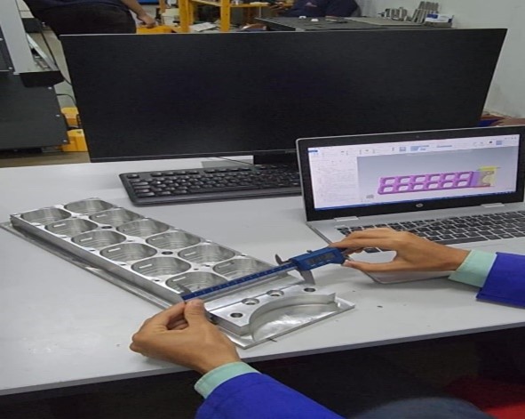 Figure 3: CNC machine setup with workpiece
 Figure 4: Machining process during finishing stage
This repetitive cycle of machining and validation provided a clear understanding of how even minor adjustments in toolpath or speed can influence surface quality and dimensional accuracy.
Overcoming Challenges
Like any real-world project, this one came with its challenges.
The first major challenge was optimizing toolpath transitions between cavities. Rapid movements could increase cycle time or risk tool collisions. By adjusting toolpath linking and retract settings, I managed to create smoother transitions that reduced air-cutting time and enhanced overall machine efficiency.
The second challenge involved chip evacuation during deep pocket machining. Chips tended to accumulate, affecting the finish and sometimes increasing tool wear. I resolved this by optimizing step-down depths and improving coolant flow, ensuring better heat management and surface integrity.
These solutions not only prevented potential tool damage but also significantly improved productivity and surface quality, demonstrating how critical small process optimizations can be in achieving professional results.
Results and Achievements
By the end of the project, the mold was successfully machined and fully met the required dimensional and surface specifications. The finished component displayed excellent precision, and the machining process proved highly efficient.
Using MasterCam’s simulation and optimization tools, I was able to reduce machining time by around 20%, all while maintaining tool life and part quality. The consistency between the multiple cavities confirmed the success of the workflow and the reliability of the process parameters chosen.
 Figure 5: Final machined mold – top and side views
This experience gave me a deep appreciation for the connection between digital preparation and physical execution. Every toolpath decision made in Mastercam was directly reflected in the quality of the machined component, proving that true manufacturing precision begins long before the machine starts cutting.
Key Lessons Learned
This project reinforced several key lessons that I believe are valuable for any aspiring manufacturing engineer:
Mastercam is more than a programming tool. It’s a complete digital environment that links design intent with machining execution.
Optimizing toolpaths and cutting parameters directly impacts productivity, surface finish, and tool longevity.
Real-world machining projects are the best way to connect theoretical knowledge with practical problem-solving, where even small decisions can lead to significant performance gains.
Conclusion
Working on the multi-cavity mold project at AEM was a defining experience in my journey as a mechanical engineer. It showed how powerful and essential computer-aided manufacturing (CAM) tools like Mastercam are in today’s precision-driven industries.
From simulation to real machining, every step required attention to detail, creativity, and a problem-solving mindset. This project not only improved my technical capabilities but also strengthened my passion for digital manufacturing, where precision, efficiency, and innovation come together to turn ideas into tangible, high-quality products.

Technician in mechanical engineering at AEM Ait Melloul Electromécanique
Youness Oubnai is a specialized technician in mechanical engineering, focusing on studies and methods in mechanical manufacturing. He is currently completing an internship at AEM Ait Melloul Electromécanique, where he applies his technical expertise in machining and production processes.
Latest posts by Youness Oubnai (see all)
- Machining a Multi-Cavity Mold with Mastercam - 23 October 2025
Subscribe
0 Comments
Oldest
