Have you ever stood near a massive industrial furnace or a roaring campfire? You do not need to touch the flames to feel the intense heat radiating outward. In high-temperature turbomachinery, your engine components experience the exact same phenomenon.
As gas turbine temperatures continue to push physical boundaries, thermal management is no longer just about fluid flow. It is about survival. If you ignore how heat radiates between components, you are setting yourself up for unexpected thermal stresses, under-designed cooling channels, and premature component failure.
Let us look at how modern simulation tools help us master this complex thermal balance without bringing our workstations to a grinding halt.
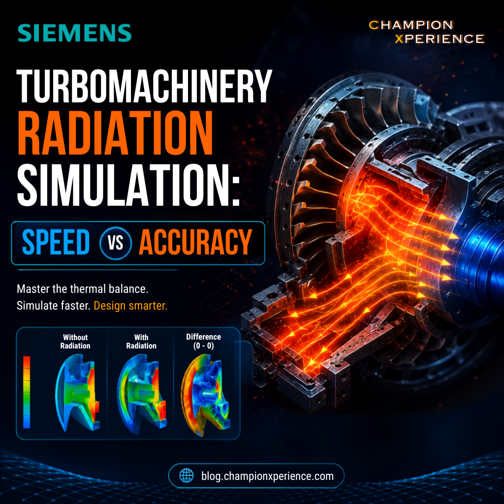
In high-performance turbomachinery, we often focus heavily on convection. We spend hours refining blade cooling passages and optimizing secondary flow paths. However, in enclosed, low-flow regions like compressor cavities and rotor-stator seals, convection is incredibly weak.
In these stagnant zones, radiation heat transfer becomes the dominant mechanism. Heat radiates from the hot turbine discs directly to cooler structural components. If your simulation models ignore this exchange, your localized temperature predictions will be dangerously low.
Even a minor temperature underestimation of 10 to 15 degrees Celsius can slash the predicted fatigue life of a critical rotor disc in half. To design reliable engines, we must capture these radiative interactions during transient mission phases.
If radiation is so critical, why do thermal engineers often hesitate to include it in every run? The answer lies in a geometric parameter called the View Factor.
A view factor is a purely geometrical value that defines how much one surface “sees” another surface . Unlike conduction, which only requires solving equations between neighboring mesh elements, radiation requires every surface to talk to every other visible surface.
As your mesh density increases, the number of surface-to-surface interactions scales exponentially. Calculating these view factors for a complex, full-3D gas turbine model creates a massive mathematical matrix. This bottleneck can easily turn a quick overnight simulation into a multi-day computational headache.
Historically, this forced engineers into a frustrating compromise. You either had to settle for highly simplified 2D models that missed critical circumferential variations, or wait days for a high-fidelity 3D simulation to finish.
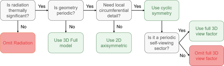
Fortunately, you do not have to choose between speed and accuracy. By applying intelligent modeling strategies, we can achieve near-3D accuracy at a fraction of the computational cost.
This is your “ground truth.” You model the entire geometry in full 3D and calculate all view factors exhaustively. While this provides the highest accuracy, you should reserve this approach for final design validation rather than daily design iterations.
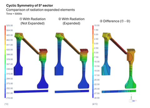
Most turbomachinery designs are inherently periodic. Instead of modeling a full 360-degree rotor, you can simulate a single sector, such as a 5-degree or 45-degree slice. However, standard cyclic symmetry struggles with radiation because surfaces outside your slice still radiate heat into it.
To solve this, advanced solvers use Radiative Rotational Periodicity (also known as expanded elements). This technique mathematically replicates the full 360-degree radiative environment
around your small sector. You get the speed of a small model with the physical accuracy of a full 3D simulation.
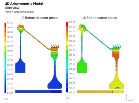
When you are in the early stages of a project, speed is everything. Reducing your geometry to a 2D cross-section assuming perfect rotational symmetry allows you to run dozens of design iterations in minutes. While 2D models cannot capture localized circumferential variations, they are perfect for whole-engine modeling (WEM) and rapid screening.
The hardware you use matters just as much as your modeling strategy. Traditional CPU-based solvers struggle with the heavy parallel math required for radiation ray tracing.
By shifting these calculations to modern GPUs, the game changes completely. Graphics cards are built for massive parallel processing, making them incredibly efficient at tracing millions of thermal radiation rays simultaneously. Recent developments in solvers like Simcenter STAR-CCM+ have proven that native GPU acceleration can slash simulation pre-processing and solve times from hours to minutes .
Using GPU-accelerated Monte Carlo radiation models allows you to handle highly complex geometries with millions of surface elements without experiencing the traditional performance bottleneck.
To help you decide which approach fits your current design phase, we have summarized the trade-offs below:
| Modeling Approach | Accuracy Level | Computational Speed | Best Used For |
| Full 3D Reference | Highest | Slowest | Final design sign-off and critical hot-spot validation |
| Cyclic Symmetry (with Periodicity) | Near-3D High | Fast | Detailed component optimization and cavity analysis |
| 2D Axisymmetric | Moderate | Extremely Fast | Early-stage screening and whole-engine thermal matching |
By combining cyclic symmetry, targeted simplification, and GPU-powered solvers, you can keep your design cycles fast and your engines running cool. How is your team currently tackling high-temperature radiation challenges in your CAE workflows? Let us know in the comments below!
This guide is based on insights from the official Siemens Blog .