
© 2023 Created by blog.championxperience.com
Introduction
In January 2026, Autodesk released a major update to Fusion software, which introduced a new design philosophy – Intent-Driven Design. This new version significantly expands project management capabilities, improves collaboration, and increases transparency across design processes.
The update is also a clear nod to users experienced with other CAD systems (such as SOLIDWORKS, Inventor, Solid Edge, etc.), which traditionally follow a bottom-up design workflow.

Intent-Driven Design
Starting with this release, Autodesk provides three modeling environments in Fusion: Part, Assembly, and Hybrid, each with its own capabilities and limitations.
Intent-Driven Design offers the following advantages:
-
Improved performance
-
Better organization of features and components
-
Greater clarity in the browser and timeline
-
Increased stability in assembly modeling and simulation
-
Support for different design philosophies and the ability to mix modeling techniques
-
Elimination of the risk of working on the wrong component
-
Fewer clicks and removal of unnecessary design steps
-
Easier distinction between working on components and working with components
-
Parallel collaboration by multiple users on separate components within the same project
The first noticeable change after updating the software is the new New File dialog, which allows you to select the project environment (design intent).
Part Design
Part Design is an environment that provides all tools required for precise, parametric modeling of individual components—from basic solid features, through surface and sheet metal tools, to advanced automation and mesh editing.
Key benefits of modeling individual components include a shorter and more readable timeline, a better-organized browser, and the elimination of accidental edits to the wrong component. This approach accelerates part modeling and reduces the risk of unnecessary errors.
When creating a new file, the dialog allows you to choose the part type: standard or sheet metal. Selecting a sheet metal part opens the file directly in the Sheet Metal workspace. Choosing a standard part does not prevent sheet metal modeling—creating geometry using sheet metal commands will automatically convert the file into a sheet metal part.
Created components can easily be sent to an assembly file (existing or new) or converted to another project type as the design evolves.
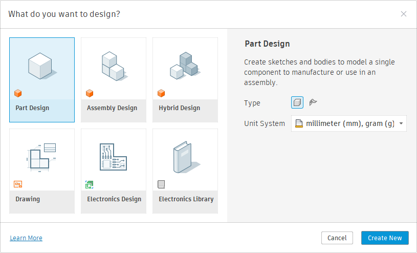 Figure 1. New Part Design
Assembly Design
Assembly mode is used to combine multiple components (parts and subassemblies) into a larger structure (for example, a machine) and to manage relationships—both static and kinematic—between them.
It also allows the creation of local components by activating modeling tools (Tools → Modeling). Components placed in an assembly can be edited locally in context, without opening separate files.
The main advantages of Assembly Design include a clear and readable timeline, an organized browser, and improved performance during assembly creation and simulation.
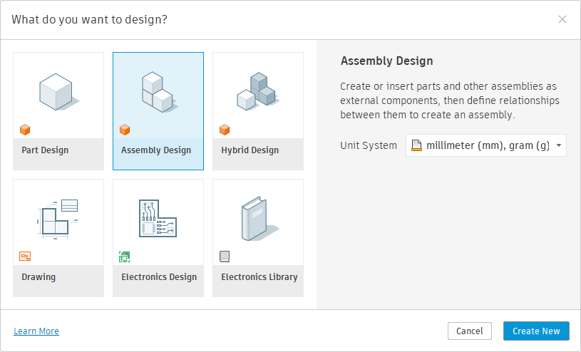 Figure 2. New Assembly Design
Hybrid Design
The Hybrid environment combines tools for modeling component geometry and assembling them within a single file. This is the workflow known from the previous Autodesk Fusion design philosophy.
If you want to continue using Fusion exactly as before, Hybrid mode is the right choice.
Its strengths include high modeling flexibility, easy editing, adaptability, simple parameter linking, and the ability to create advanced configurations.
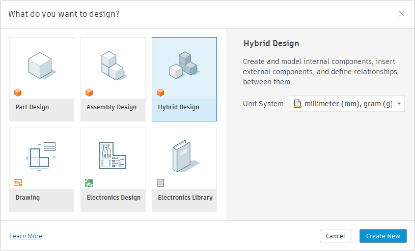 Figure 3. New Hybrid Design
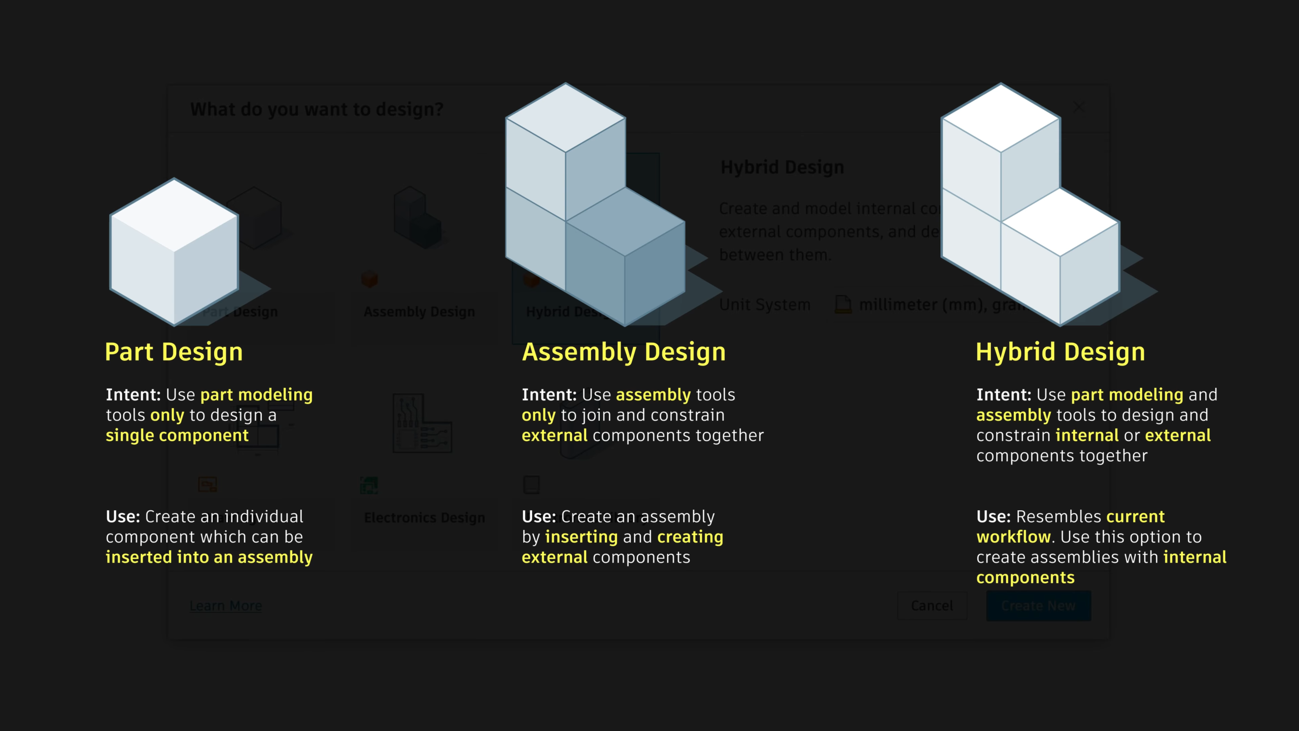 Figure 4. Modeling environments Preferences (Source: Autodesk)
Important Note on Sheet Metal Modeling
Sheet metal should not be modeled in a multi-body workflow. This is especially important in Hybrid projects. Sheet metal components do not support converting bodies into new, independent components or generating flat patterns for all bodies.
In such cases, the only workaround is to create new derived parts and transfer geometry from individual bodies—an approach that contradicts the idea of hybrid modeling. Therefore, sheet metal parts must always be modeled as separate components from the very beginning.
Choosing the Design Mode
The Dialog Window
The welcome dialog described above appears in three cases:
-
When launching the program
-
When creating a new tab
-
When creating a new document from the menu (File → New…)
In addition to the modeling environments, it also allows you to start working on a 2D technical drawing or an electrical design project.
Default Mode
Fusion allows you to create a new file using the keyboard shortcut Ctrl + N. This method skips the welcome dialog and opens a new file using the default project type defined in the user preferences (Account → Preferences → General → Default Project Type).
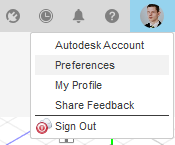
Figure 5. User Preferences in Autodesk Fusion
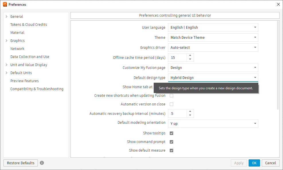 Figure 6. Selecting the default project type
Changing the Design Environment
Fusion allows easy switching between modeling environments. If the default mode does not match your goals, or if the project evolves and requires a different intent, you can quickly change the environment in the document settings (Browser → Document Settings → Project Type).
Keep in mind that it is not possible to convert an Assembly (or Hybrid) project into a Part project if the assembly already contains inserted or defined components.
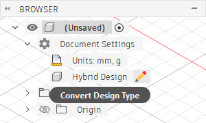 Figure 7. Changing the project type
Outlook
Configuration
Fusion allows modeling multiple variants of a design within a single file. The configuration table makes it possible to create product families, size ranges, or distinguish manufacturing stages within one document.
Designing individual components and assemblies in separate files also allows configuration, but only within those files. Intent-Driven Design currently does not support configurations based on simultaneous variable features at both component and assembly levels.
Autodesk is working on a comprehensive configuration system, but at the moment there is no confirmed timeline—or guarantee—of its release. Therefore, for concept design, prototyping, and highly flexible projects, the Hybrid environment is still recommended.
Parametrization
Fusion enables parameter exchange and relationships between different files. However, the Hybrid mode remains significantly easier and more user-friendly in this regard.
Although Autodesk is developing Global Parameters to improve cross-document parameter workflows, no concrete declarations have been made yet. As a result, for highly parametric designs, Hybrid mode remains the most effective modeling approach.
Summary
The latest Autodesk Fusion update is undoubtedly a revolution in the CAD/CAM/CAE market and a major step forward for the software. Fusion now offers three distinct modeling environments that can be optimally selected based on specific design goals.
This makes it easier to organize project structure and manage data, work with a shorter and more readable timeline, and maintain a cleaner browser. In some cases, it can significantly improve performance and stability. It also simplifies the transition for users coming from other CAD systems or working across multiple platforms.
Good luck!
More information and tips can be found on the Autodesk Community forum. I also encourage you to watch the introductory videos on Intent-Driven Design.

Autodesk Expert Elite | CAD/CAM Consultant at Mech-Design Kacper Suchomski
Kacper Suchomski is an Autodesk Expert Elite & Mentor with over eight years of experience in CAD design and production implementation. As the founder of Mech-Design, he helps engineers and manufacturers turn innovative ideas into manufacturable, production-ready solutions.
Latest posts by Kacper Suchomski (see all)
- How Engineers Use Sketch Driven Pattern in Autodesk Inventor - 16 March 2026
- Intent-Driven Design in Autodesk Fusion: What Changed in 2026 - 8 February 2026
Subscribe
0 Comments
Oldest
