
© 2023 Created by blog.championxperience.com
This article presents a comprehensive overview of the Machine Design Workflow utilizing ZW3D. It systematically discusses various stages of the design process, including Part Design, Part Drawing, Part Configuration, Assembly Design, Assembly Drawing, Direct Editing, Sheet Metal Design, Structural Design, and Part CAE Simulation.

The objective is to provide a structured understanding of how ZW3D facilitates an integrated and efficient workflow for mechanical product development.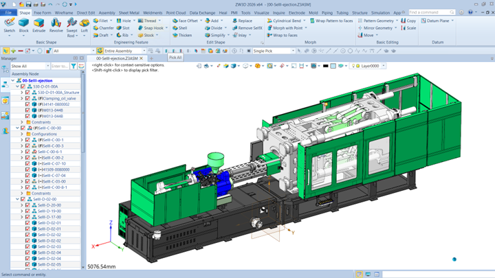
Part Design
In the Part Design stage, ZW3D follows a workflow similar to that of other mainstream 3D CAD systems, beginning with sketch creation and progressing through essential 3D modeling features such as Extrude and Revolve. It also provides a comprehensive set of engineering features, including Chamfer, Hole, and other refinement tools. Furthermore, ZW3D allows users to customize shortcuts, such as radial menus and toolbar configurations, enabling a more efficient and personalized design experience.
Part Drawing
In the Part Drawing stage, ZW3D enables users to efficiently create 2D documentation from 3D models. The process typically begins with the insertion of the main view, followed by projection views as required. You can generate a full section view to reveal internal details and add isometric views to better illustrate complex geometries. ZW3D also lets users easily modify view attributes and adjust isometric orientations directly within the 2D drafting environment.
Users can apply dimensions either automatically or manually, just like in other professional CAD systems. ZW3D streamlines the process of adding tolerances, surface finish symbols, and feature control frames. It also automatically annotates specific engineering features, such as holes.
By utilizing properly configured drawing templates, users can standardize and preserve essential production notes to ensure consistency and compliance with manufacturing requirements.
Part Configuration
ZW3D also supports parametric design, enabling the creation of multiple size and configuration variations for a single product model. Users can define these configurations manually within the software or utilize Excel-based configuration tables to efficiently generate and manage design variations. The Excel integration allows seamless data synchronization between ZW3D and external spreadsheets, facilitating rapid updates and improved control over parameter-driven designs.
Assembly Design
During the Assembly Design process, ZW3D provides an intuitive environment for component placement and constraint definition. In the latest version, ZW3D 2026, the assembly constraint workflow has been significantly enhanced to improve usability and efficiency. The system also offers comprehensive tools for interference detection and the creation of exploded views, which can be generated either automatically or manually, depending on design requirements.
For Bill of Materials (BOM) management, ZW3D allows users to organize and edit BOM data directly within the 3D environment, even before generating 2D assembly drawings. The 3D BOM manager enables customization of column structures, inclusion of specific attributes, and batch editing of multiple components simultaneously—such as modifying material properties. To further streamline data management, the 3D BOM can be exported to Excel for rapid bulk editing and synchronized back into ZW3D.
Additionally, ZW3D facilitates design review and communication through multiple export formats. One practical option is the HTML export, which allows stakeholders to view 3D assemblies directly in a standard web browser—without the need for additional software installation. The interactive HTML viewer provides functionalities such as assembly tree navigation, automatic explosion, sectioning, measurement, and component isolation, supporting effective collaboration and design validation.
Assembly Drawing
Upon completion of the assembly design, the workflow proceeds to the Assembly Drawing stage. In this phase, ZW3D enables users to place exploded views, apply automatic balloon annotations, and generate a corresponding 2D Bill of Materials (BOM) directly linked to the balloon references. The balloon attributes can be fully customized, and users may also include component image legends to enhance visual clarity during design review and verification.
Furthermore, the 2D BOM can be exported to Excel format, allowing non-CAD users—such as procurement or production teams—to review component information, including part numbers and associated images, without requiring ZW3D installation. To accelerate the creation of detailed drawings for individual components, ZW3D offers an Auto-Drafting function capable of generating multiple part drawings automatically with minimal user input.
For efficient data exchange and collaboration, ZW3D allows simultaneous multi-format export of drawing files, such as PDF and DWG, in a single operation. This capability minimizes repetitive tasks and significantly improves overall workflow productivity and document management efficiency.
Data Exchange and Direct Edit
ZW3D provides comprehensive multi-CAD interoperability, supporting the import of numerous file formats from major CAD platforms such as SolidWorks, CATIA, Siemens NX, Creo, Solid Edge, Inventor, and Rhino, without incurring additional licensing costs. Once imported, models originating from external systems can still be modified and refined, even in the absence of their original feature history.
Through its robust Direct Editing capabilities, ZW3D enables users to perform intuitive and efficient modifications on imported 3D geometry. This functionality allows engineers to seamlessly integrate and edit legacy or third-party designs, thereby enhancing design flexibility and facilitating cross-platform collaboration within heterogeneous CAD environments.
Sheet Metal Design
In addition to the mainstream design workflow, ZW3D also offers specialized industry-specific applications, such as Sheet Metal Design. Within this module, users can create standard sheet metal features, including tabs and flanges, with full control over parameters such as the K-factor or custom bend allowance tables.
Beyond basic operations, the sheet metal environment in ZW3D supports advanced forming features such as louvers, dimples, and, in the latest version, a newly introduced vent feature. Upon completion of the sheet metal design, users can readily generate unfolded 2D layouts along with their corresponding overall dimensions. You can export the unfolded geometry directly to DWG or DXF formats, ensuring seamless integration with downstream manufacturing and fabrication processes.
Structure Design
ZW3D includes a dedicated Structure Design module that provides comprehensive support for frame and structural modeling workflows. The process begins with a specialized 3D Frame Creation tool, which significantly accelerates the development of wireframe structures. The module also incorporates an extensive profile library, featuring both aluminum and steel profiles that can be easily applied to the design.
Profiles can be assigned efficiently using window or cross-selection methods, allowing multiple wireframe segments to be selected simultaneously. ZW3D further enhances the structural design process with automated joint processing, ensuring accurate and robust connections between structural members. For managing intersecting or overlapping structures, the Face Trim tool enables users to trim multiple members concurrently. Notably, even after trimming, users can modify the applied profiles, and ZW3D will automatically retain previous trim results, thereby eliminating the need for rework.
In addition, the module provides a dedicated Structural Element library containing a range of accessories and fittings to complement structural assemblies. Upon completion of the design, ZW3D can automatically generate a Structural Bill of Materials (BOM) that compiles all relevant attributes for each member. This BOM can be organized to produce comprehensive procurement lists or detailed cutting lists, facilitating efficient fabrication planning and production management.
Animation
Based on the defined assembly constraints, ZW3D enables users to simulate mechanical motion within assemblies, providing a clearer understanding of the kinematic behavior and facilitating effective product visualization. This functionality is particularly useful for analyzing machine movements and demonstrating operational mechanisms during design evaluation or product presentations.
As an example, ZW3D can accurately represent the motion of complex systems such as an injection molding machine clamp mechanism, including detailed components like gears and other connected parts, allowing engineers to validate motion sequences and detect potential design issues early in the development process.
CAE Simulation
To ensure that all components are strong and function properly, it is essential to conduct Finite Element Analysis (FEA). ZW3D provides a built-in CAE simulation module that is easily accessible and designed to support engineers in evaluating part strength and structural integrity. Prior to initiating the analysis, users can perform model simplification to reduce computational complexity and optimize simulation time.
Within the simulation environment, ZW3D offers an intuitive workflow suitable for design engineers, encompassing key steps such as material selection, constraint definition, load application, and mesh generation with user-friendly control over mesh settings. Once the setup is complete, users can efficiently run the analysis to obtain accurate simulation results.
Additionally, ZW3D allows users to visualize load animations for a clearer understanding of stress distribution and deformation behavior. To complement the analysis, a comprehensive automatic report generation feature is available, enabling users to quickly compile and document simulation results for validation and presentation purposes.
Summary
ZW3D offers a comprehensive and fully integrated solution for machine design, covering every stage from conceptual modeling to final validation. Its core capabilities include Part Design and Part Drawing for accurate 3D modeling and detailed 2D documentation. The Part Configuration tools enhance efficiency by managing parametric variations and product families with ease.
For system development, Assembly Design and Assembly Drawing simplify complex creation processes, interference checking, and documentation with intelligent BOM management. ZW3D also supports seamless Data Exchange and Direct Editing, allowing modification of imported geometry from multiple CAD platforms without compromising design flexibility.
Specialized modules like Sheet Metal Design and Structure Design expand ZW3D’s reach into industry-specific workflows. Combined with Assembly Animation and built-in CAE Analysis, engineers can visualize motion, validate performance, and identify design issues early. Altogether, ZW3D delivers an integrated CAD/CAE environment that streamlines the entire machine design process—enhancing efficiency, collaboration, and product quality.

Senior Application Engineer at ZWSOFT
Candra Diningrat is a Senior Application Engineer at ZWSOFT Indonesia, specializing in ZW3D technical solutions, training, and customer support. He leads enablement programs for reseller partners, develops localized training materials, and supports multi-country technical initiatives. Recognized for excellence, he has earned multiple awards, including Employee of the Year 2023 and several ZWStar and Advocacy Awards for his outstanding contributions.
Latest posts by Candra Diningrat (see all)
- Why ZW3D is a Complete Solution for Modern Machine Design - 5 November 2025
Subscribe
0 Comments
Oldest
