
© 2023 Created by blog.championxperience.com
Have you ever stood at the top of a towering water slide, looking down at the twisting fiberglass tube, waiting for the green light to plunge? It is an adrenaline rush like no other. But as you feel the cool water rushing beneath you, reducing friction so you can slide safely around tight curves, have you ever wondered about the engineering keeping that water flowing?
Behind every thrilling splash is a complex web of piping, valves, and pumps. Designing these systems requires precise calculations to ensure safety, efficiency, and consistent water flow. Today, we are going behind the scenes to see how engineers use Simcenter Flomaster to model and optimize water slide hydraulic systems, ensuring the perfect ride every single time.
From Wooden Chutes to Closed-Loop Hydraulic Marvels
Water slides have come a long way since their early days. In the early 20th century, the first documented water slides were simple wooden or metal structures built next to pools. They were often steep, dry, and lacked the safety standards we expect today. The introduction of fiberglass in the mid-20th century changed everything, allowing for smooth, complex, and enclosed shapes.
Modern water parks are massive operations. A single large park can require over a million gallons of water to run. Because of this, sustainability is a major priority. According to industry data, modern parks are highly efficient, recycling 97% to 98% of their total water volume. This is achieved through closed-loop hydraulic networks that continuously collect, filter, and pump the same water back to the top of the slides.
The Physics of the Climb: Overcoming Gravity
The core challenge of any water slide hydraulic system is moving massive amounts of water up high towers against gravity. Water cannot flow uphill on its own, so mechanical energy must be introduced.
The process starts at the bottom reservoir or splash pool. Powerful electric pumps draw water from the pool, pushing it through a complex network of vertical pipes, bends, and flow control valves. Once the water reaches the top platform, it is discharged onto the slide surface. From there, gravity takes over, creating a thin, fast-moving layer of water that minimizes friction between the rider and the slide.
If the pump pressure is too low, the water will not reach the top. If it is too high, the system faces unnecessary wear and energy waste. This is where 1D thermo-fluid simulation tools like Simcenter Flomaster become indispensable for hydraulic engineers.
Modeling the Network in Simcenter Flomaster
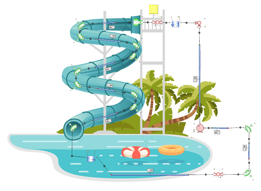
Using Simcenter Flomaster, engineers can build a complete digital twin of the water slide’s hydraulic network. The software allows designers to drag and drop components—such as pipes, bends, junctions, valves, and pumps—from a validated catalog to represent the physical layout.
To design an efficient system, engineers break the simulation process down into three distinct phases: Flow Balancing, Steady-State Simulation, and Transient Simulation.
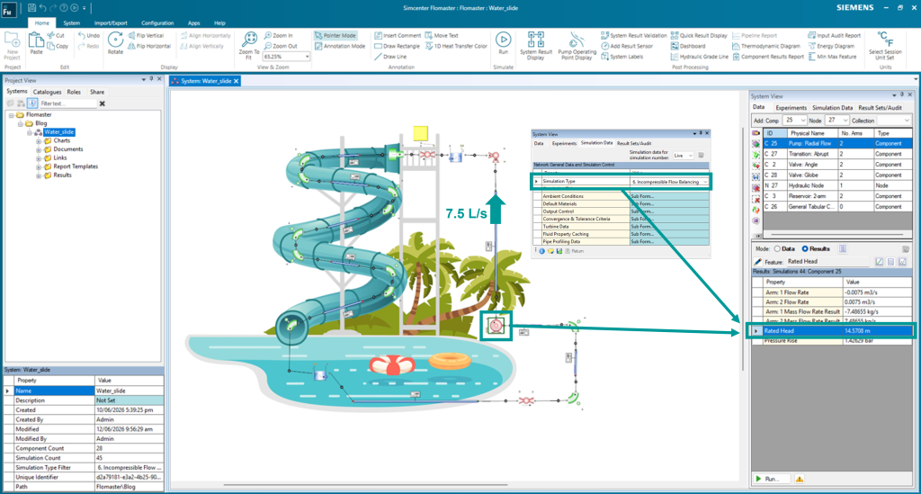
1. Flow Balancing: Finding the Perfect Pump
Before purchasing hardware, engineers must determine the exact specifications of the pump. Simcenter Flomaster features a Flow Balancing capability that simplifies this process. Instead of guessing pump sizes, engineers input the target volumetric flow rate required for the slide—for example, 7.5 L/s (0.0075 m³/s)—and the software automatically calculates the exact pump head required to overcome elevation changes and friction losses.
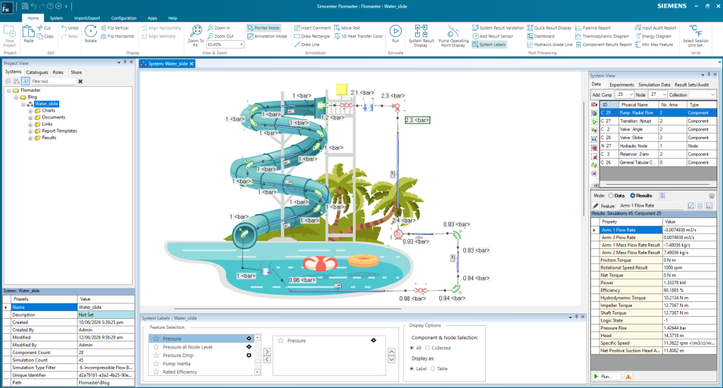
2. Steady-State Simulation: Verifying Normal Operations
Once the pump is selected, a steady-state simulation provides a snapshot of the system operating under normal, stabilized conditions. This analysis helps engineers verify that pressures across the entire network remain within safe limits and that water is distributed evenly to all discharge points. It is the perfect phase to identify localized pressure drops or bottlenecks in the piping layout.
3. Transient Simulation: Analyzing Dynamic Events
In the real world, hydraulic systems are rarely static. Valves open and close, pumps start up, and power outages occur. These dynamic events can cause sudden pressure surges, commonly known as water hammer, which can rupture pipes or damage valves. Transient simulation allows engineers to observe how the system behaves over time during these events, ensuring that the physical piping can withstand sudden changes in flow.
Comparing Simulation Phases in Simcenter Flomaster
To understand how these three simulation types work together during the design process, let’s look at their primary roles:
| Simulation Phase | Primary Objective | Key Parameters Analyzed | Engineering Value |
| Flow Balancing | Determine system sizing and pump requirements. | Required pump head, target volumetric flow rate. | Prevents over-specifying or under-specifying the pump. |
| Steady-State | Analyze stabilized operating conditions. | Static pressures, flow distribution, friction losses. | Verifies that all components operate safely within design limits. |
| Transient Simulation | Capture dynamic system behavior over time. | Pressure surges, water hammer, valve opening/closing times. | Prevents structural fatigue and catastrophic pipe failures. |
Visualizing the Results for Better Decisions
Interpreting complex hydraulic data is made easier through Simcenter Flomaster’s visual analysis tools. Engineers can use color-mapped result displays directly on the schematic to see pressure intensity and flow direction. Integrating virtual sensors allows designers to track variables, such as a control valve’s fraction of opening, over a timeline. This visual feedback ensures that any design modifications can be quickly verified and implemented.
Whether designing a simple backyard slide or a massive multi-rider funnel slide at a world-class water park, 1D fluid simulation ensures that the engineering is as robust as the ride is thrilling.
How is your team tackling complex fluid network designs? Have you integrated 1D system simulation into your CAD/CAE workflows yet?

Content Manager at ChampionXperience
Sharing insights, tutorials, and industry updates on CAD, simulation, engineering, and digital transformation technologies.
Latest posts by ChampionXperience Team (see all)
- Simcenter Flomaster: Water Slide Hydraulic Design Guide - 25 June 2026
- Siemens Industrial AI: Smart Glasses on the Shop Floor - 24 June 2026
- Aras InnovatorEdge: Model-Driven PLM for Enterprise AI - 23 June 2026
Subscribe
0 Comments
Oldest
