

From the machinery manufacturing sector to the aerospace industry, sheet metal design and production always maintain their importance. In this blog post, we will examine the complete ZW3D sheet metal workflow in detail, including how to perform a design from scratch, how to export the DXF format for laser cutting, and how to create a technical drawing showing the bend direction and angles for press brake bending.

Before moving on to the hands-on video tutorial, it is beneficial to have a ZW3D license so that you can follow and apply the steps. If you are in the transition process to ZW3D and want to test the program and its capabilities with a sample application, you can test ZW3D FREE for 30 days using the link below.
If you are ready, let’s get started!
Pro Tip: When starting a new sheet metal design, selecting the file type is important. When you select the file type as Sheet Metal, the Sheet Metal Node appears in the History Manager area. This node allows you to define the Sheet Metal Attributes.

If you select the file type as Part instead of Sheet Metal, you will not see the node belonging to these attributes. This does not prevent you from designing sheet metal, but you will need to redefine parameters such as thickness, bend radius, and relief every time you use a sheet metal command. To save time, selecting the correct file type when designing sheet metal will make things easier for you.
Pro Tip: The workflow in sheet metal designs continues by making additions or subtractions after creating a base. ZW3D offers a separate command for creating a base and a separate command for creating a flange. It offers the Extrude Tab command for closed profiles (for example, a rectangular sketch), and the Extrude Flange command so you can create a flange from an open profile (for example, a U sketch) or a closed profile. When you use a closed profile, the Extrude Flange feature forces the creation of a rip to allow the flange to be unfolded. If you wish, it also allows you to decide from which region and with how many millimeters of gap the rip will be made.
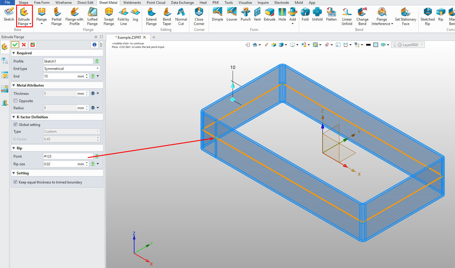
Thanks to this command, you can create hollow sheet metal boxes with a closed form and a specific sheet thickness, and you can also get their flat patterns.

Pro Tip: Another feature that distinguishes ZW3D from its competitors in sheet metal is the Forming Tools. In traditional CAD programs, forming tools are library-based. They allow you to shape your sheet metal by dragging and dropping ready-made form geometries located in the library. In addition, if your manufacturing machines have different forming tool shapes, you can add these 3D models to the library and use them.
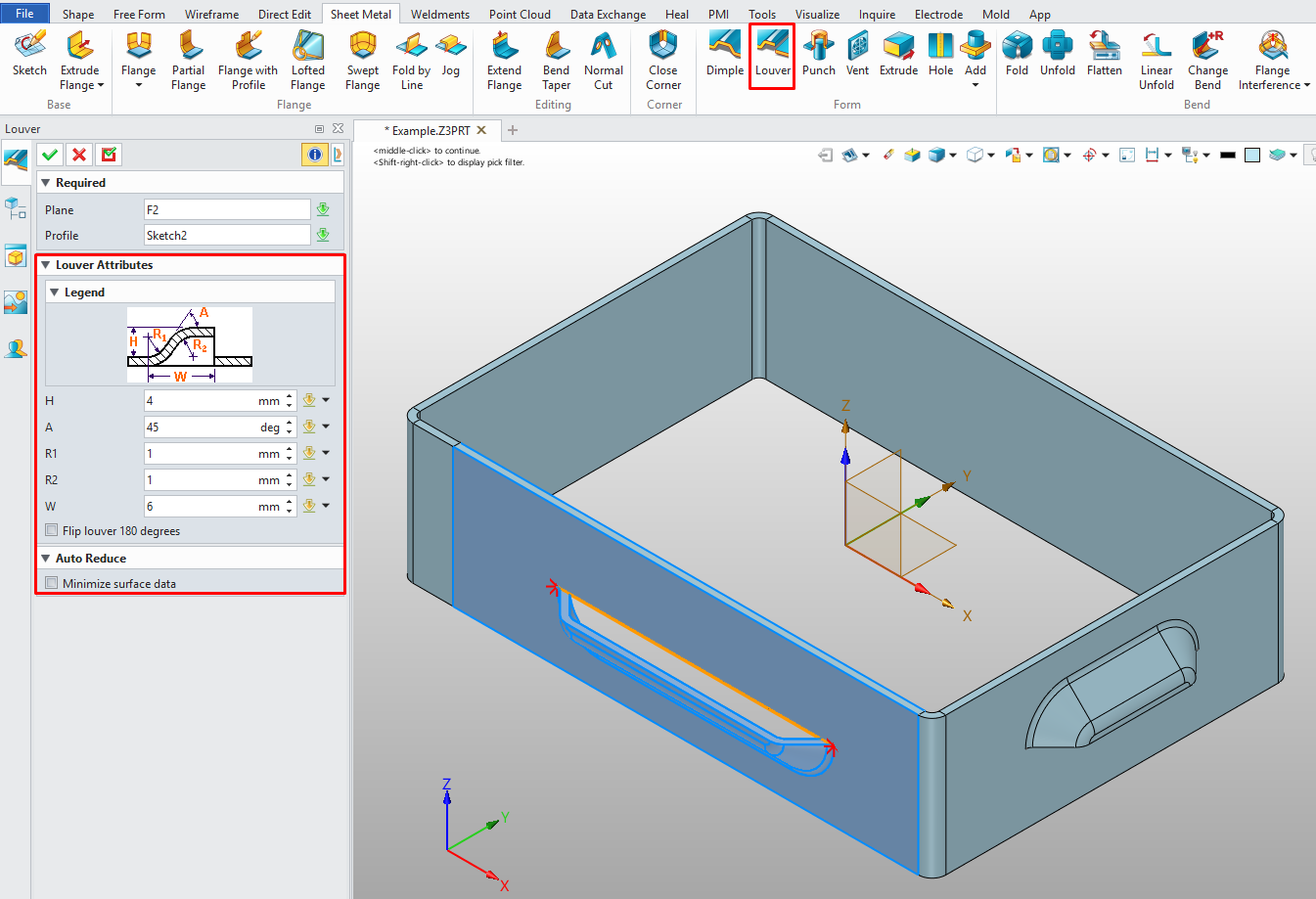
ZW3D, on the other hand, allows you to create form shapes using commands instead of a library. In the Case Study example in the video, you can create a pierced emboss form shape with the Dimple command. You can also create a standard emboss form shape using the Plain Dimple option located within the same command. If you want to create a Louver, it is enough to simply create a line indicating the position and length of the louver you will create, and provide the parameters within the command.
Pro Tip: In cases where you will perform a fold or jog operation with a line, the direction in which the sheet metal will bend is indicated by the arrows in the coordinate system. If the direction of the red arrow (X-axis) is pointing left and the blue arrow (Z-axis) is pointing up, you can understand that the edge of the sheet metal will lift upwards and bend to the left.
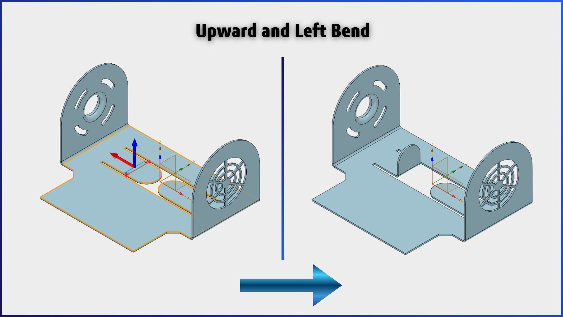
If the direction of the blue arrow is downwards, you can understand that the sheet will bend downwards.

You can manage the direction of these arrows from the window of the relevant command. You have two different options to manage the directions.
This changes the direction of the red arrow (X-axis). This option is important because a wrong selection could keep the part to be folded stationary and fold your main part, instead of folding the intended part upwards or downwards. When examining the direction of the red arrow in the picture, it points to the area outside the sheet metal part that needs to be folded, rather than looking inside it. When this happens, you end up doing the exact opposite operation.
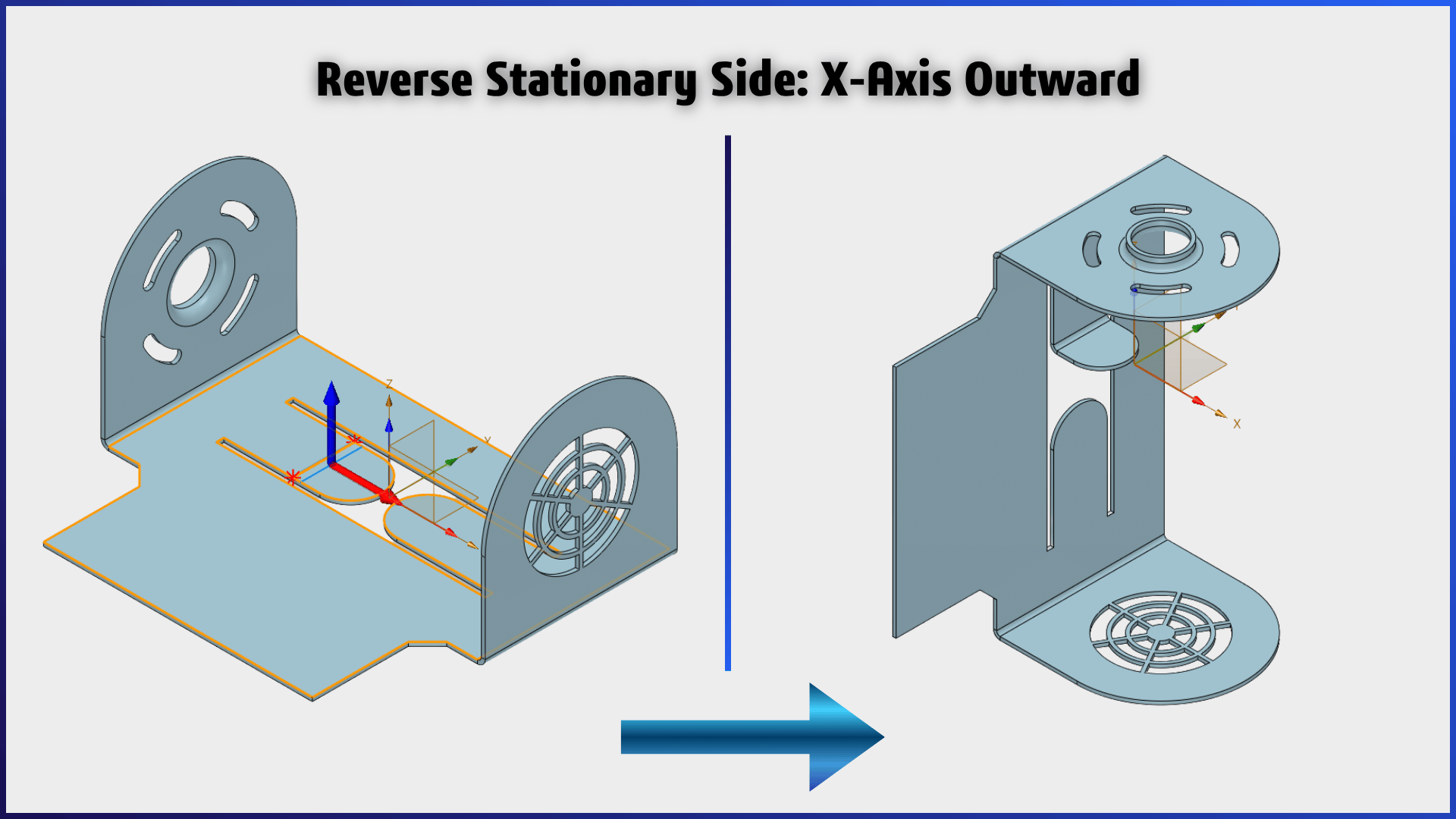
This changes the direction of the blue arrow (Z-axis). This indicates whether the bending direction is downwards or upwards.
Note: Remember that the colors of the arrows represent the axes, and they may vary depending on the orientation of your part. It is also worth remembering that the fold by line and jog commands do not allow mirroring operations in many CAD programs.
Pro Tip: The Punch command offers two different options. In the first option (Punch from shape), you need to create a 3D model directly at the location where you want the punch to be while working on your sheet metal part. This generated model must be a solid body. The second option (Punch from file) allows you to use a 3D model that you created in a different project.
As an example, a cube is placed on an Extrude Tab as a punch shape.
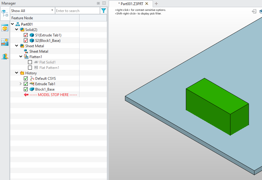
1.To create a punch, the 3D model you created must penetrate into the sheet metal. This is a requirement, because this is the only way you can specify the depth.

2. The base direction you select on the sheet metal is important. If you positioned the punch part on top of the sheet metal and you select the top surface as the base, a punch will be created equal to the thickness of the punch model inside the sheet. (Reference Image No. 1)

Conversely, if you select the bottom surface as the base, ZW3D creates a punch that matches the portion of the punch model extending above the sheet. (Reference Image No. 2)
3. You can leave open areas on the punch model.

Pro Tip: Instead of the logic of gathering many operations under a single command, ZW3D has preferred to offer operations that are likely to be edited as separate commands. If you’re coming from a different CAD program, these commands may feel unfamiliar at first. However, once you become familiar with them, you’ll see how they make your workflow more flexible. For example, if you want to create a flange with a specific start and end distance, it offers you a separately presented command, the Partial Flange command.

Pro Tip: You can unfold the sheet metal from the automatically generated Flatten option located right below the Sheet Metal Attributes in the History Manager. There are two sub-options within Flatten. When you activate Flat Solid, the flat pattern of your sheet metal part becomes visible. This flat pattern is a graphic. This means that you cannot perform operations on it. When you activate the Flat Pattern option, you can see the area covered by the unfolded sheet, meaning the bounding box dimensions, along with the arrows showing the bend directions of the sheet.
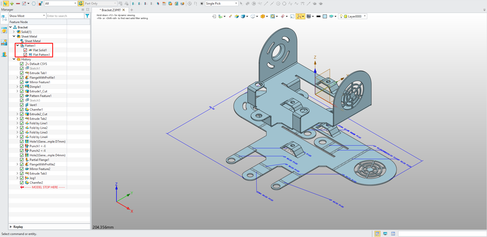
Now you know how a sheet metal model is designed from scratch with ZW3D. Continuing with the sheet metal workflow, in addition to the DWG/DXF outputs for laser cutting, we need a technical drawing file. The drawing should include the dimensions used to inspect the part after laser cutting, as well as bend notes indicating the required bend angles and bend directions.
To be able to export a DXF/DWG file, you can right-click the Flat Pattern option inside the Flatten folder located in the History Manager and select the Export DWG/DXF option from the opening menu.
After selecting the file name and location from the save screen and confirming, the following screen appears. Since it will be used for manufacturing, we choose the DXF (ASCII) format.
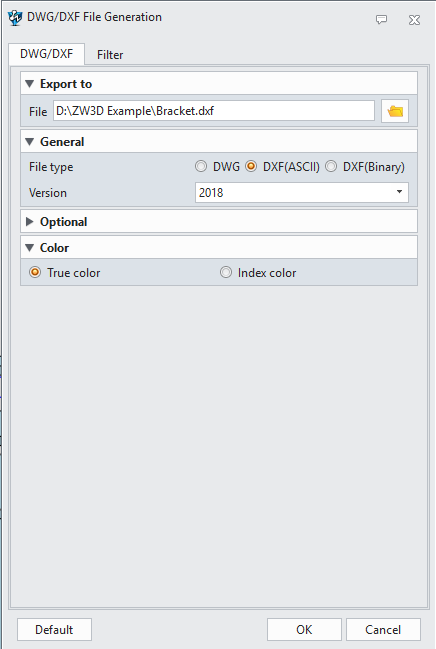
If you do not want certain elements to appear in the DXF output, you can exclude them from the Filter tab. For example, since we will provide the bend directions and dimensions as a technical drawing, we check the Text and Dimension options from the filter to exclude them from the DXF output.

You can view the DXF output with the ZWCAD software, and if there are details you want to add or remove before sending it to laser cutting, you can edit it with ZWCAD.

Thanks to the Auto Drafting feature, ZW3D can automatically create technical drawings based on the selections you make. With the ZW3D Wukong 2027 release, the Auto Drafting feature has improved even further. Since the new version became available while I was writing this blog post, I decided to use ZW3D 2027 for this demonstration.
You can use the Auto Drafting feature in two different ways. While in the 3D View screen, you can quickly create your technical drawing by right-clicking and selecting the Auto Drafting command. To access more advanced options and make selections, you can also reach the Auto Drafting command from the Tools tab on the Ribbon.
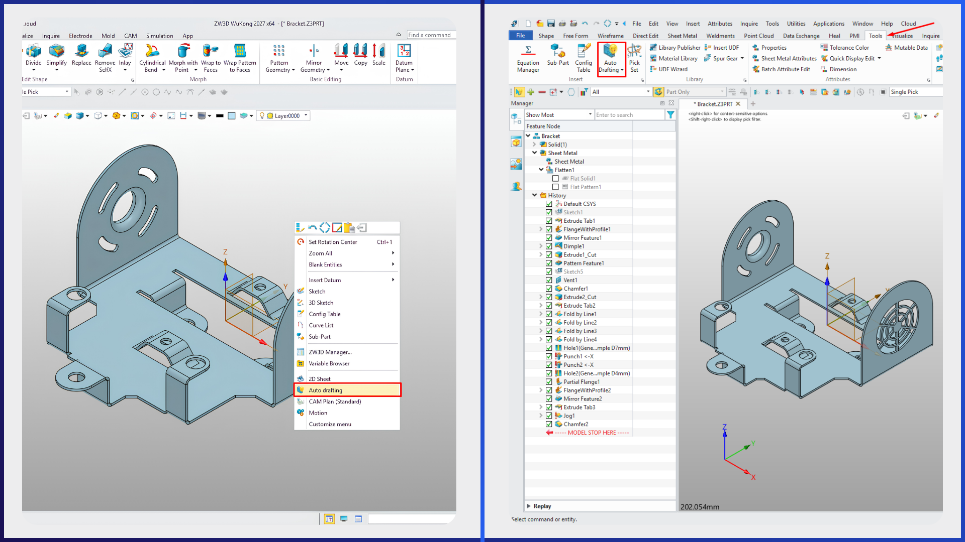
When you select the Auto Drafting command located on the Tools tab, a settings window welcomes you. Here, you can select the file or folder for which you want to create a technical drawing. When you select a folder, you can have the technical drawings of all the files inside it created automatically. You can set the technical drawing template belonging to the part or assembly. From the preferences (gear icon), you specifically need to select the “Flatten view for sheet metal” option for the flat pattern view of your sheet metal parts. You can select your dimension styles and assembly-specific settings according to your needs.
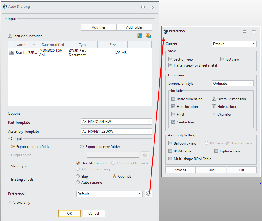
The video below shows how ZW3D automatically creates the technical drawing for the Bracket part. When you confirm the command shown above, SOLIDWORKS automatically generates six standard model views and adds dimensions based on your document preferences. When the process is complete, you can finish your technical drawing by deleting the views you do not want according to your needs and adjusting the positions of the dimensions for a better view.
Additionally, we created a separate sheet to inform the operator about the bending sequence and angles during the press brake process after laser cutting, and we added the flat pattern view to our sheet. By enabling the bend lines and bend notes in the view, we completed the technical drawing process.
In this blog post, we examined the sheet metal workflow using ZW3D in detail through a sample model. You can use the link below to get more information about ZW3D and try it for free for 30 days.
Explore ZW3D & Start Your 30-Day Free Trial

