

You might think that 2D design has lost its importance with the rise of 3D modeling, but that is not the case. Many companies have long-established 2D workflows and standards that have developed around them. Even after adopting 3D modeling, they continue to use 2D drawings for manufacturing. 2D design also remains important for layout-focused work, particularly factory and floor plans.
In this blog post, we will take a detailed look at how to place an electrical enclosure, designed using the sheet metal tools in ZW3D, into a floor plan in ZWCAD using the DWG format. We will also examine how to update the DWG drawing in ZWCAD when the model’s features are modified in ZW3D.
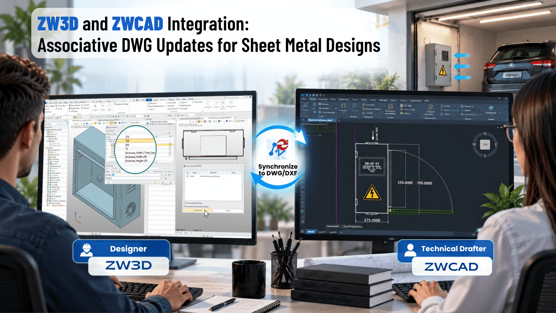
In the traditional workflow, a designer or engineer working with 3D modeling saves the sheet metal model in DWG format and sends it to the 2D CAD team. A draftsman on the team then uses the DWG file in the floor plan, adding the explanatory notes, warning symbols, and dimensions required by the relevant standards.
Up to this point, the process is straightforward. However, when a design change is requested and the necessary modifications are made to the 3D model, a new DWG file has to be generated. The draftsman must then repeat the work carried out during the initial process, particularly the dimensioning. This can create a considerable additional workload.
When transferring DWG data from ZW3D to ZWCAD, a linked DWG file can be generated through the Drafting environment in ZW3D. Dimensions and annotations can then be added to the DWG drawing in ZWCAD.
When a change is required in the 3D model, there is no need to generate a new DWG file as in the traditional workflow. Instead, you can use the synchronization feature to update the existing DWG drawing. The dimensions added in ZWCAD are also automatically updated to reflect the new values.
Another useful aspect of this feature is that changes made in ZW3D Drafting, such as creating sections or adding annotations, can also be applied to the DWG drawing in ZWCAD using the synchronization command.
With this feature, ZWSOFT aims to establish a synchronization bridge between 3D and 2D teams. You can learn more about this new ZW3D feature in the video below. (To watch the Turkish version, please select Turkish from the language options.)
Scenario:
Designer: Designs an electrical enclosure for a villa in ZW3D. To use it in the floor plan, transfers the enclosure’s top view to ZWCAD using the Link DXF/DWG feature.
Drafter: Incorporates the villa’s floor plan into the DWG drawing and makes the necessary adjustments. Adds the standard information required for the electrical enclosure and includes the necessary dimensions. Submits the drawing for preliminary approval.
Project Manager: Reviews the plan and notices that the vent’s air intake direction is facing the garage door. Provides feedback directly to the designer, requesting that the vent direction be changed and the enclosure dimensions be adjusted so that the door takes up less space.
Designer: Makes the required changes in ZW3D and updates the DWG file to reflect the revisions in the floor plan. Once the DWG is updated, the revised drawing is ready for the drafter to review.
Drafter: Reviews the updated drawing, adjusts the air intake direction to match the new vent orientation, and adds the enclosure door with the required dimensions. Submits the revised plan to the project manager for approval.
Project Manager: Reviews the revised plan and approves the enclosure design.
Pro Tip: To automatically generate drawing views of your model, right-click an empty area in the ZW3D Part environment and select Auto Drafting. Alternatively, for more control over the process, you can select the Auto Drafting command from the Tools tab on the ribbon. Since we only needed the top view of the electrical enclosure, we chose the traditional manual method instead of Auto Drafting. To do this, we selected 2D Sheet from the right-click menu.
Pro Tip: Both drawing creation methods require you to select a title block template. However, since we wanted to place the top view of the electrical enclosure directly into a villa’s floor plan, we selected Blank Template. This prevents a title block from appearing in the ZWCAD environment.
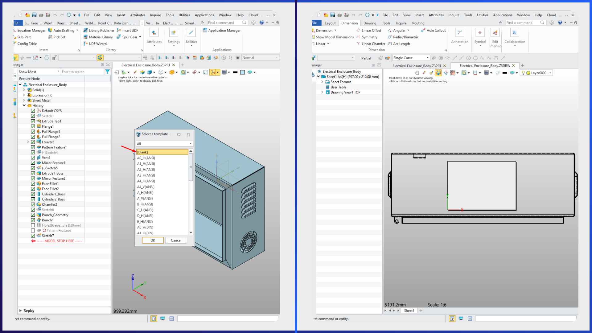
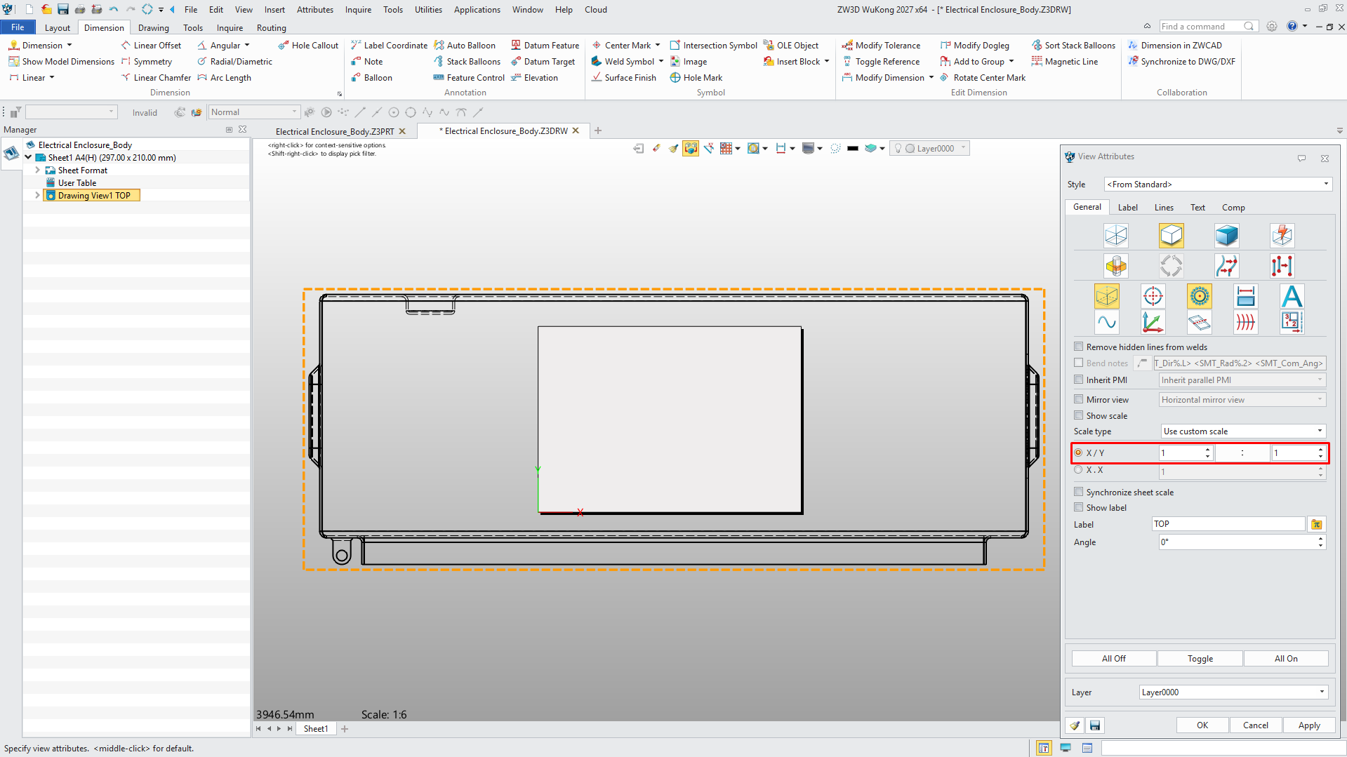
Pro Tip: Since the electrical enclosure will be used in a floor plan, make sure its drawing view is set to a “1:1″ scale. Double-click the view to open the View Attributes dialog, where you can set the scale and choose which properties should be displayed in the DWG drawing, such as centerlines and hidden lines.
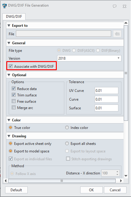
Pro Tip: When transferring the drawing to ZWCAD as a DWG file, the most important thing to check is that the Associate with DWG/DXF option is enabled. With this option selected, you can update the DWG in ZWCAD when changes are made to the model.
Pro Tip: Whenever you make a change to the model designed in ZW3D, you can update the DWG file from the Drawing environment using the Synchronize to DWG/DXF command. In the Synchronize to DWG/DXF dialog, you can select the sheets you want to update.
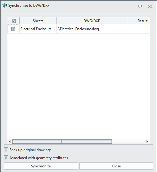
The dialog also includes the Back up original drawings and Associated with geometry attributes options. These options provide the following functionality:

When this option is disabled, the changes are written directly to the original file.
Pro Tip: You do not need to have ZWCAD open to update your DWG file. After the update, simply open the DWG in ZWCAD to see the changes. This is a useful feature for teams that manage their data over a shared network.
Pro Tip: When adding dimensions to the drawing, use the Annotate dimensioning commands instead of the Parametric dimensioning commands. This is because the drawing does not contain independent DWG data. It behaves much like a block, and dimensions can only be added for display purposes. They do not allow you to modify the geometry. Any design changes must be made in ZW3D.
Pro Tip: You can use the Ctrl+3 keyboard shortcut to open Tool Palettes in ZWCAD. You can then drag and drop items from the palette directly into your drawing.
Pro Tip: To change the reference plane of a sketch in ZW3D, right-click the sketch and select Relocate from the context menu. After selecting a new face or plane in the command, the view automatically aligns perpendicular to that plane (if the Orient the active view option is enabled). Use the Up option to determine whether the sketch appears above or below, and the Origin option to position the sketch at the origin and fix its location. Once you confirm, the sketch will be relocated to the selected face or plane.
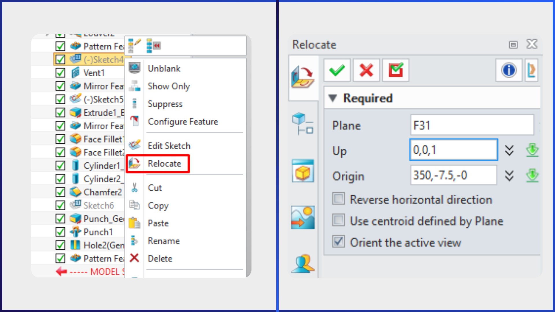
Pro Tip: The Vent command is not directly tied to the sketch plane. If you change the plane associated with the sketch, you can update the vent’s position by editing the Vent feature and selecting the new face in the Face field. As an additional trick, since the vent is not tied to a sketch plane, you can change the face on which the vent is located simply by editing the Vent feature and selecting a different face—without having to change the sketch plane. The important thing here is that the faces must be opposite and facing each other.
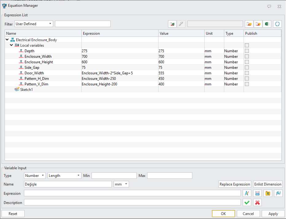
Pro Tip: When designing in ZW3D, you can link dimensions that may change to variables. This allows you to manage them directly from a single interface without having to edit the sketch or feature. If you need to define relationships between values, you can use the Equation Manager to create formulas between variables.
In this blog post, we explored in detail how DWG synchronization between ZW3D and ZWCAD works through a practical scenario. By acting as a bridge between 3D modeling and 2D design, two disciplines that have been closely connected for years, the synchronization feature helps improve collaboration between teams and save time.
To learn more about ZW3D and try it free for 30 days, use the link below.
Explore ZW3D & Start Your 30-Day Free Trial

