

You can change a model with no feature tree in Solid Edge as fast as one you built yourself. The tools that make it possible are the Steering Wheel and Live Rules, which Solid Edge 2026 shows in the Design Intent panel.
Every engineer gets this file sooner or later. A supplier sends a STEP, a colleague leaves, or an old project comes back as a dumb solid. Customers then ask for the usual tweaks: taller bosses, more draft, a hole moved a few millimetres. The old answer was to rebuild the part. The better answer is to edit the faces directly and let the software keep the geometry consistent.
In this post I take a real molded housing with zero history and make five production-style changes to it.
The test part is Housing Base.par, a polypropylene base from the Solid Edge training set. It is a proper molded part: a drafted outer wall, a large bore, ribs, a lip for the lid, and two screw bosses with Ø3.96 pilot holes.
What matters is what PathFinder shows. Under Synchronous → Features there is one item, BodyFeature 2. No sketches, no extrudes, no rounds. This is exactly what you get after importing a STEP or Parasolid file, so everything below works the same on supplier data.
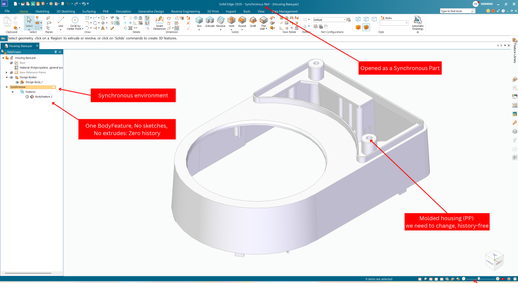
Figure 1. The imported housing. PathFinder holds a single body feature: there is no history to roll back or edit.
Two things to check before you start:
The Steering Wheel is the 3D handle that appears on whatever you select. Every move and rotate in this post starts from it, so learn its parts once.
Select a single planar face and you get a simplified wheel: just the primary axis. Select a feature’s worth of faces (here, the boss cylinder plus its top) and the full wheel appears.
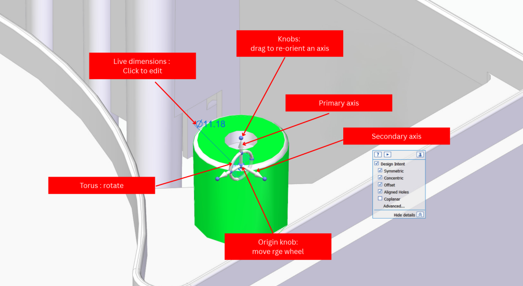
Figure 2. The full Steering Wheel on the boss. The live Ø11.18 dimension is clickable too.
| # | Part | What it does |
| 1 | Primary axis | Click it, drag or type a distance: translates the selection along that arrow. |
| 2 | Secondary axis | Same, along the second direction. |
| 3 | Torus | Drag or type an angle: rotates the selection about the primary axis. |
| 4 | Tool plane | Click it to move freely in that plane. |
| 5 | Origin knob | Drag to re-position the whole wheel, for example onto a hole centre or an edge midpoint. |
| 6 | Knobs (blue spheres) | Drag to re-orient an axis, for example to align it with an edge. |
| 7 | Live dimension | Solid Edge reads the size of the selected face (Ø, R, angle). Click the value to edit it. |
The habit that saves the most time: click an axis, then type the value instead of dragging. The drag only sets the direction.
The request: the lid supplier changed screws, and both bosses need 8 mm more engagement.
Watch the preview before you commit. I selected one face, but the rear boss is growing too, and the status bar reads Design Intent adjusting 4 faces.
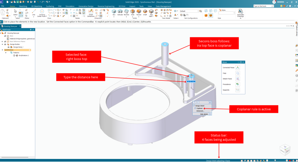
Figure 3. Live preview of the move. Coplanar picked up the rear boss because both tops sit on the same plane.
That is Live Rules at work. Solid Edge saw that the two boss tops are coplanar and assumed I want them to stay that way. Here that was exactly right: the screws are the same length, so both bosses should grow together. One selection, one value, both bosses fixed.
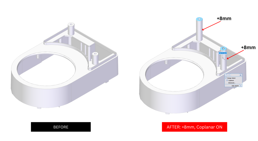
Figure 4. Before and after. Both bosses are 8 mm taller; nothing else on the part moved.
Live Rules are guesses about intent. Usually good ones, but not always what you want. Say only the right-hand boss needs the longer screw. Same selection, same command, one difference: during the move, untick Coplanar in the Design Intent panel.
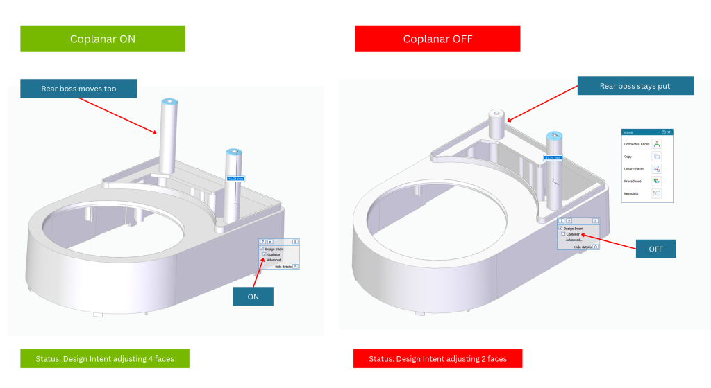
Figure 5. Same move, Left: Coplanar on, both bosses move. Right: Coplanar off, only the selected boss moves.
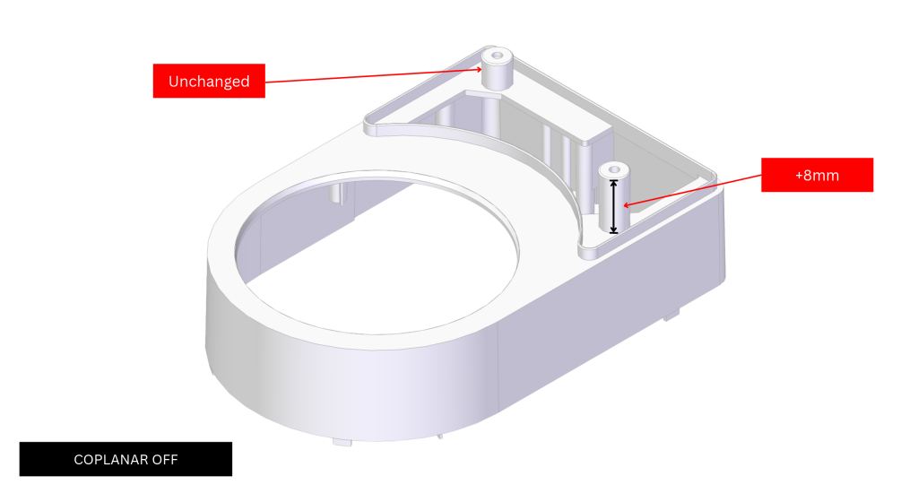
Figure 6. Result with Coplanar off. The rear boss keeps its original height.
Two habits worth building here:
The request: the toolmaker wants more draft on the outer wall for a cleaner release from the mold.
This is where synchronous editing earns its keep. There is no Draft feature in the tree to edit, but Solid Edge does not need one. Click the curved outer wall and it is recognised as a cone with a 1.00° half-angle. The draft is read straight from the geometry.
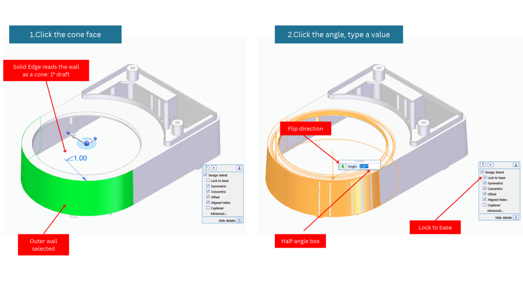
Figure 7. Left: the wall is recognised as a 1° cone. Right: the half-angle box, with the direction toggle and the Lock to base option.
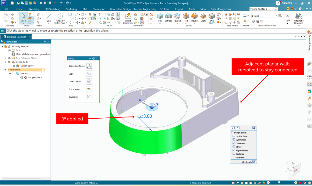
Figure 8. Draft now 3.00°. The flat side walls re-solved so the body stays closed.
Note the Lock to base option that appears in the Design Intent panel for this edit. As the name says, it holds the base edge of the cone where it is while the angle changes. That is what you want when the draft must hinge at the parting line and the footprint cannot grow. My footprint was not critical, so I left it clear; try both on your part and compare.
I made the same check on an inner wall segment: Solid Edge read that one as a 1° cone too. A part built with consistent draft gives you consistent handles.
The request: the right-hand screw clashes with a PCB component. Move the boss 6 mm along the wall and open the pilot hole from Ø3.96 to Ø4.50 for a different screw.
To move a boss you have to take all of it: cylinder, top face, hole and base fillet. The quickest way is a fence (window) select: drag a box that fully encloses the boss. Faces that cross the box edge, like the floor, are left out.
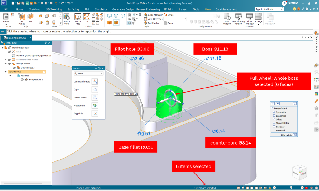
Figure 9. Fence selection grabbed 6 faces. Solid Edge shows the boss Ø11.18, the hole Ø3.96 and the base fillet R0.51 as live dimensions.
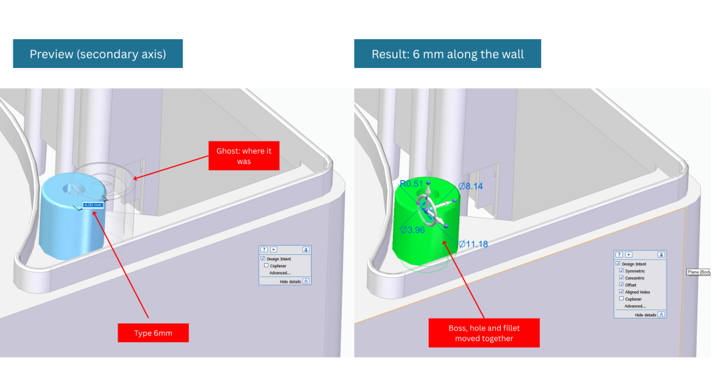
Figure 10. Left: the preview, with a ghost of the original position. Right: the boss, its hole and its fillet moved as one. The floor where it stood is filled in.
That last detail is the point of synchronous modelling. Solid Edge removed the boss from its old position, healed the floor and rebuilt it at the new one. No sketch, no pattern, no delete-and-redo.
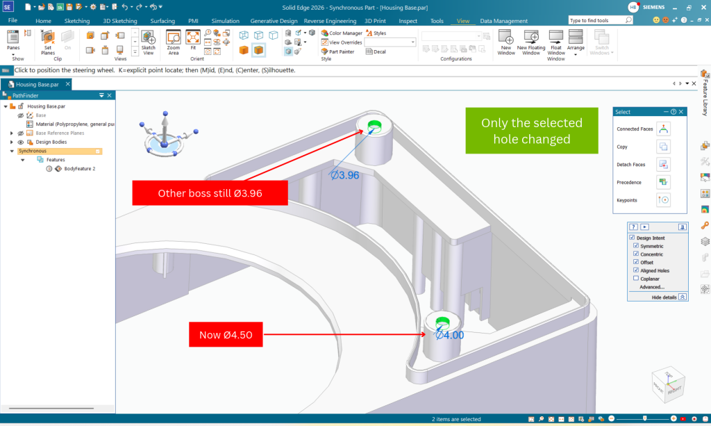
Figure 11. Left: editing the diameter in place. Right: the moved boss is now Ø4.50 while the rear boss keeps Ø3.96.
The small Design Intent panel shows only the rules that apply to the current edit. Click Advanced… in it to get the full toolbar at the bottom of the window. In this mode the model goes translucent and the faces affected by each rule are colour-coded, with a legend on the right.
Every button has a single-key shortcut you can press mid-command. These are the ones I confirmed from the tooltips in Solid Edge 2026:
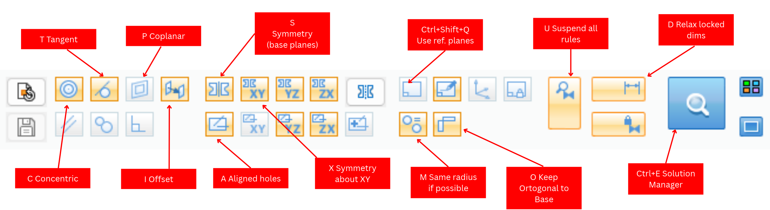
Figure 12. The advanced Design Intent toolbar with the shortcut for each rule.
| Key | Rule | What it holds |
| C | Maintain concentric faces | Hole stays centred in its boss |
| T | Maintain tangent faces | Fillets stay tangent to their walls |
| P | Maintain coplanar faces | Faces on the same plane move together |
| I | Maintain offset faces | Wall thickness stays constant |
| S | Symmetry about base planes | Mirror-image features stay mirrored |
| X | Symmetry about base XY plane | Symmetry about one plane only |
| A | Maintain aligned holes | Holes, cylinders and revolves on a shared axis stay aligned |
| M | Same radius if possible | Fillets keep their radius through the edit |
| D | Relax dimensions | Lets locked dimensions change for this edit only |
| U | Suspend design intent | Turns every rule off: only the selected faces move |
| Ctrl+Shift+Q | Consider reference planes | Includes reference planes when applying rules |
My rule of thumb: leave everything on, watch the face count, and press U when you need a surgical change to exactly what you picked.
Live Rules infer intent; 3D (PMI) dimensions let you state it. On a history-free part this is how you put back the critical numbers from the drawing, and then drive the model from them.
The request: the lid’s screw pattern is 90.00 mm hole to hole. The imported part measures 88.91 mm.
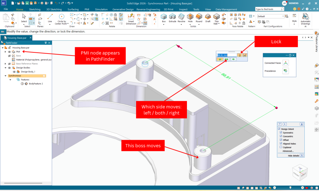
Figure 13. Editing a 3D dimension. The arrows choose which side moves; the lock freezes the value against later edits.
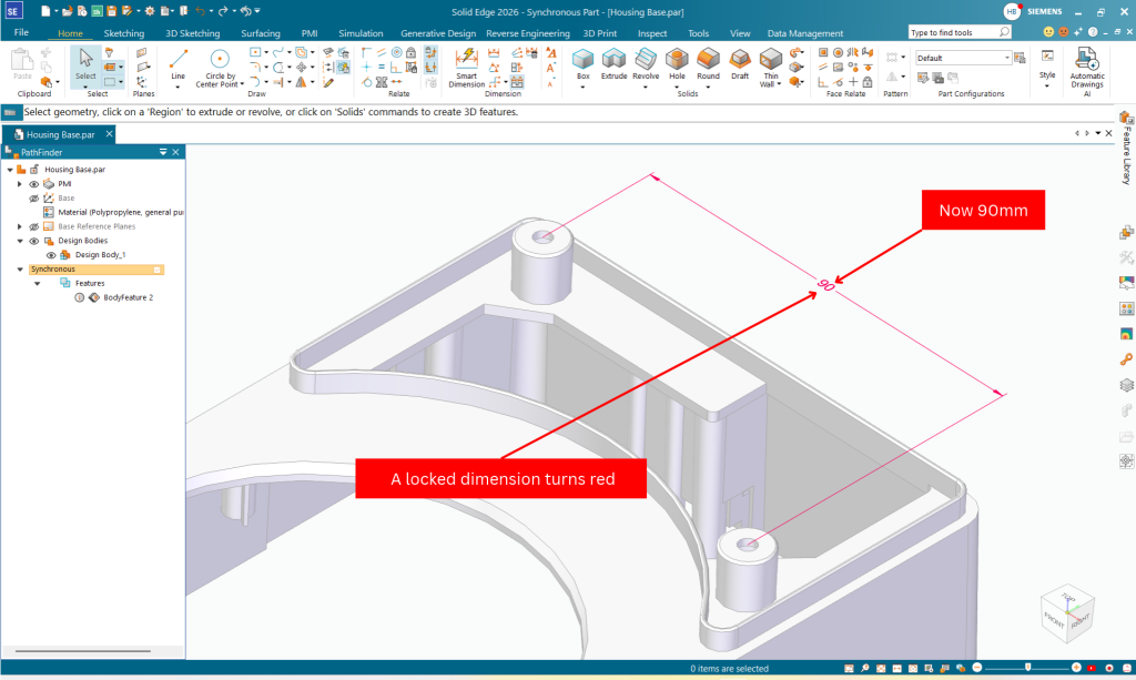
Figure 14. The pattern is now 90 mm. The right-hand boss moved 1.09 mm and took its hole with it.
Now click the lock on that dimension. A locked dimension turns red, and from then on Solid Edge holds that spacing while it solves any other edit. When you really do need to break it, press D (Relax dimensions) for that one edit.
This is the habit that makes synchronous parts safe to share: a handful of locked dimensions on the functional features, everything else free to change.
Solid Edge 2026 makes editing history-free models faster and easier. With the Steering Wheel, Live Rules, and 3D dimensions, you can modify imported geometry, adjust design details, and maintain critical dimensions without rebuilding the model from scratch. This makes synchronous modelling a practical solution for working with STEP files and legacy CAD data.

