
© 2023 Created by blog.championxperience.com
Introduction
Most of us are creatures of habit, especially those of us who work with 3D CAD programs like SOLIDWORKS every day. We tend to rely on the same features and modelling techniques. This is understandable whether we’re designing similar components or simply using the tools we know best.

It also reveals a little about how we learned the program. Regardless of whether you are self-taught or have been through formal training, when you are learning SOLIDWORKS you start with sketches, and with tools from the Sketch toolbar. Then with tools from the Feature toolbar, and you produce solid models.
This is how the process continues for many. You never need to look for different tools, and you certainly never need to look at the Surfaces toolbar. If you Google “SOLIDWORKS surfacing,” you will find that it creates models impossible with solid modelling tools. Most examples feature organic shapes and smooth curves.
However, hiding in plain sight are a range of surface features which can greatly assist with your day-to-day solid modelling.
We will run through a few of these surface features and see how they can be incorporated within our daily solid modelling.
Cut with Surface
![]() Cut with Surface
Cut with Surface
There is a little bit of irony that the Cut with Surface feature, as it is to be found on the Surface toolbar. However, if you customize your toolbars and look for Cut with Surface, you will find that it is listed under Features and not Surfaces. Either way, it is a simple and efficient tool. It does exactly as the name indicates and uses a surface to cut the solid.
The simplest use of Cut with Surface is to understand that SOLIDWORKS classifies planes as Surfaces and as a rule, it is better to use features than sketches.
An example would be a non-symmetrical part and to use Cut with Surface and then mirror the part to produce a symmetrical component.
 Figure 1.
However, there is more often a need to use the Cut with Surface tool in conjunction with the Offset Surface feature.
 Figure 2.
Offset Surface
 Offset Surface
The Offset Surface tool recreates a surface with a zero distant offset or generates another surface at a specified distance from the selected surface.
 Figure 3.
That surface can be used in numerous different ways. A common use is when you need to scribe a part with the shape of another part. In this case, we have an oval shaped sink which sits in a countertop. We will cut the shape out of the countertop.
As it is in an assembly, we can use Edit Part on the countertop and use Offset Surface, to recreate the selected surface of the sink the required distance from it. That distance could be a zero offset. If you do change to a zero dimension, you will see the command change from Offset Surface to Copy Surface.
We can now use Cut with Surface to create the cut.
 Figure 4.
What do we do with the Surface now that we no longer have a need for it? We could simply hide it, but it will be better to delete it. When using this combination of solid and surface bodies, SOLIDWORKS will assist by creating different folders in the feature tree for both the surface and solid bodies.
Delete/Keep Bodies
Delete/Keep Bodies
There is a Delete/Keep Bodies tool which is another feature that hides by default on another toolbar, in this case, the Direct Edit toolbar. This too can be used to remove the surface. However, you may prefer to access this tool by selecting the body from inside the Surface Bodies folder and using the Delete key on the keyboard. This will automatically launch the Delete/Keep Bodies command with the body shown selected. Hit the Enter key to confirm.
 Figure 5.
The use of Offset Surface is only limited by your unfamiliarity with it. Once you start using it, it becomes one of those go-to commands. When working with large assemblies and multiple sub-assemblies, it is helpful to work directly within the part.
As shown above, recreating a surface from one part allows you to form another part within the same context. The surface can then be used as a reference to create a sketch or a new part.
Delete Face > Delete and Patch

Delete Face
Delete Face is a versatile tool because its options expand what you can achieve with it.
Delete Face with the option to Delete is a way to change a solid body into a surface body. By deleting a face of a solid body, you lose the solid body and are left with surface body, and you will enter the realm of surface modelling. But that is for another article. Let us concentrate on how we can use this tool with a solid body.
The Delete Face with the option of Patch is one of those miracle commands. With a single command, you replace the need to use three or four other commands to achieve the same result. It is especially useful if you are working with imported data or bodies that do not have features.
For example, a drawer slide provided by the component supplier is not the correct part. You wanted a simple drawer slide, not a self-closing version. You could chase the supplier for the correct part—or have the part you need in a minute.
Using Delete Face > Delete and Patch, you can select all the faces that are not required, and it will delete those faces and patch the surfaces to retain the part as a solid body.

Figure 6.

Figure 7.
How about a sheet metal part with the wrong radius, or with holes that are not required?
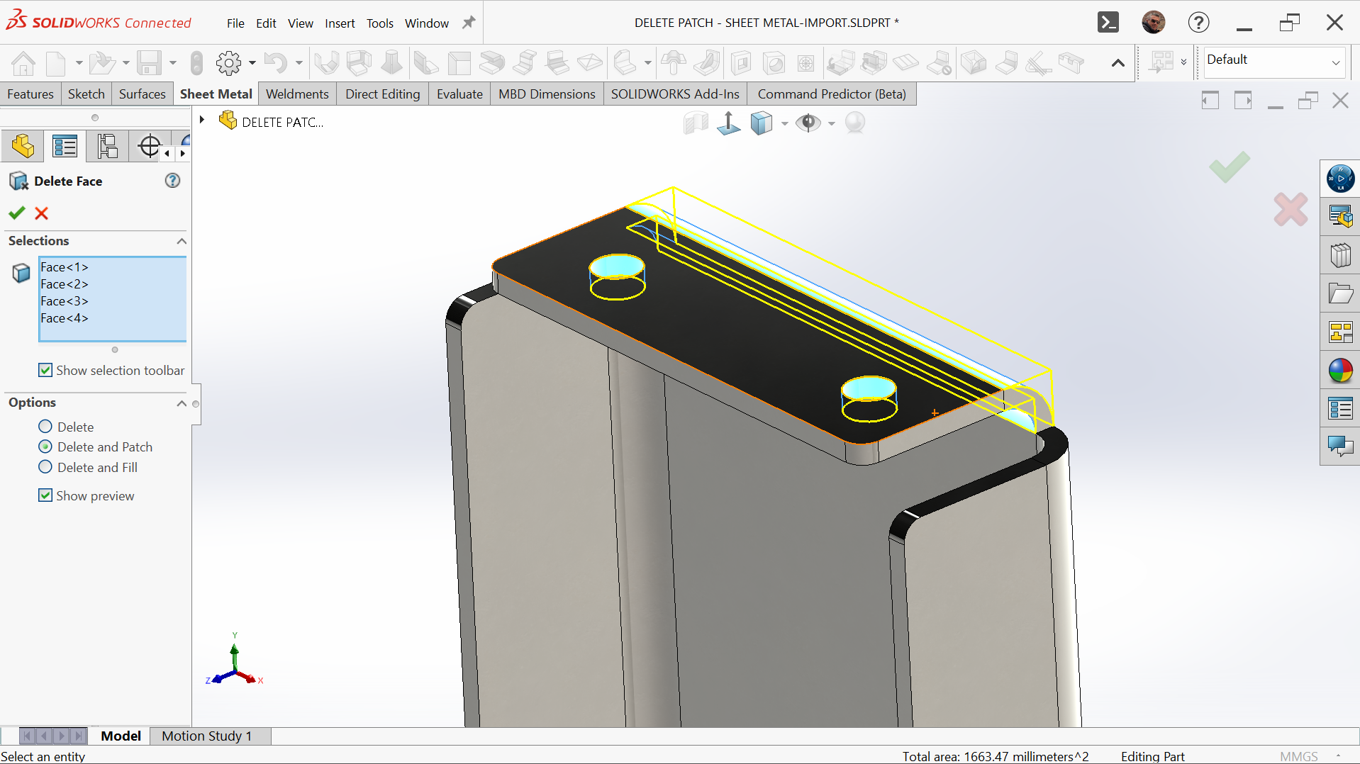 Figure 8.
 Figure 9.
The Delete Face using the Delete and Patch option is a timesaving feature with its ability to remove multiple faces and replace them with a single feature.
Delete Face > Delete and Fill
The final option, Delete Face > Delete and Fill, works like Delete and Patch but replaces multiple faces with a single face.
Many models have tangential faces of the same radius which will display an edge. This might be common where you have mirrored a part to be symmetrical. Although this might not cause issues in the model, you normally would not want the faces displayed this way.
With Delete and Fill, you can replace those faces with a single face.
 Figure 10.
 Figure 11.
You can use surface tools to assist with solid modelling. However, Delete Face > Delete and Fill has a hidden trick useful for imported models, which often suffer from translation issues. A model often develops surface issues when one program creates it, saves it in a neutral format, and then imports it into SOLIDWORKS.
It is also not unusual to have what looks like a solid model be a surface model. Using the CHECK command will highlight but not solve the issue.
 Figure 12.
Use Delete Face > Delete and Fill to fix the issue. Selecting a face not only replaces it but also checks the model in the background, sealing it and automatically creating a solid body.
 Figure 13.
Conclusion
How you model in SOLIDWORKS should constantly evolve. Over the years, new commands and options appear, and the interface changes with each release. By trying these Surface tools in your solid modelling, you may discover faster and more efficient methods than your current approach.
Product Development & Engineering at Trakka Pty Limited
Michael has over two decades of experience in designing and developing motorhomes and special-purpose vehicles. A Certified SOLIDWORKS Professional and Champion, he leads the Sydney SOLIDWORKS User Group and represents the Pacific Region on the SWUGN committee. He received the Michelle Pillers Community Contribution Award in 2019.
Latest posts by Michael Lord (see all)
- Advanced SOLIDWORKS Techniques: Using Surface Tools for Solid Modeling - 22 October 2025
Subscribe
0 Comments
Oldest
