
© 2023 Created by blog.championxperience.com
In the engineering and machinery manufacturing sectors, 3D CAD software has become the standard design tool. Companies prefer different CAD solutions depending on their budgets, sectors, and workflows.
However, manufacturing processes are not limited to design alone. Today, alongside CAD software, companies also require CAE solutions for engineering analyses and CAM software for manufacturing preparation and CNC programming. While this enables more comprehensive workflows, it can also introduce additional licensing and maintenance costs.
As the CAD market has grown, the number of alternative software options available to users has increased significantly. This competitive environment provides companies with greater flexibility in choosing solutions that better suit their needs.
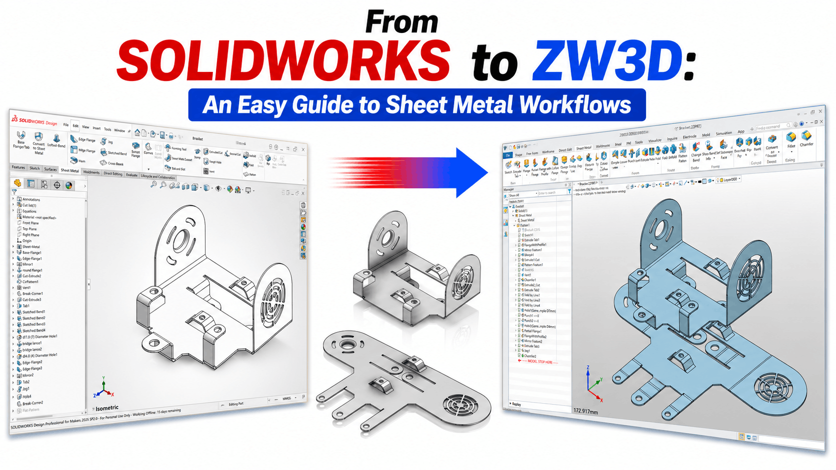
In this article, we will examine the capabilities offered by ZW3D, developed by ZWSOFT with an “All-in-One” approach, specifically in sheet metal design processes. To make the evaluation more concrete, we will also include various workflow comparisons with SOLIDWORKS, one of the industry’s popular solutions.
Our goal is not to claim that one software is superior to another; rather, it is to illustrate, through examples, the different approaches and tools that users working with sheet metal design might encounter in their daily workflows.
Comparison of Sheet Metal Commands
If you are using a different CAD program and considering switching to ZW3D, you will be able to find detailed answers to the majority of your questions in this section, at least those focused on Sheet Metal. In order for you to understand what is different in ZW3D Sheet Metal commands, we had to explain by making a comparison with a different CAD program. For this comparison, we used SOLIDWORKS, a software known for its popularity in the market, as a reference. To be able to make a comparison, we objectively examined all the commands in both software and the differences between the commands, and we turned them into a table. Before moving on to the table, I would like to touch upon some fundamental differences.
Sheet Metal
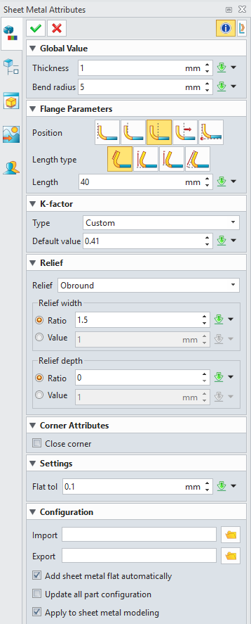
When determining the file type on the ZW3D startup screen, there is a specific option for Sheet Metal design.
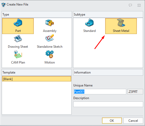
If this option is selected, a feature is added to the beginning of the History Manager area where you can specify the properties of the Sheet Metal in detail. This way, you do not have to set parameters for every new sheet metal command. In the opposite case, meaning if you choose the Part type instead of the Sheet Metal file type, an option to control the Attributes is not added to the History area.
In SOLIDWORKS, there is no such distinction on the startup screen. You can only see the properties belonging to the sheet metal when you will create or have created the first sheet metal part.
Understanding Flat Pattern Workflows in ZW3D and SOLIDWORKS
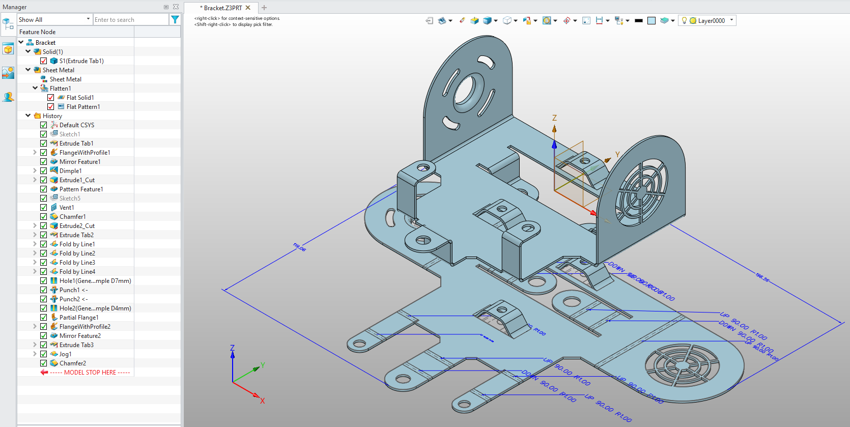
In ZW3D, when you perform the Sheet Metal flattening via the Flatten in the History Manager area or using the Flatten command located in the Sheet Metal Ribbon, it does not change the appearance of the model you designed. Instead, it brings a flattened view to a location of your choice. This view is a graphical component. It does not allow you to perform operations on it.
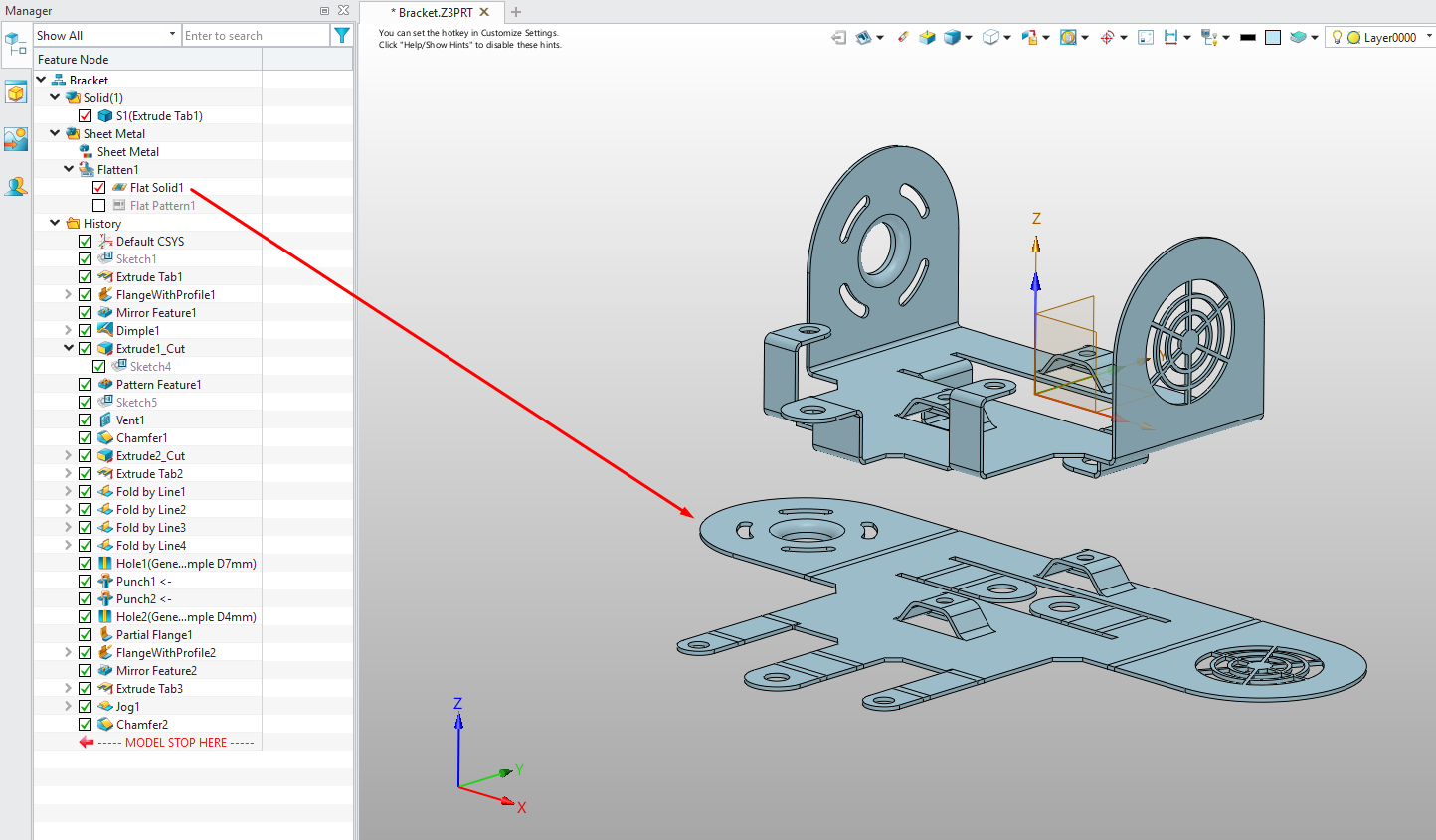
Furthermore, when you activate the Flat Pattern option located inside the Flatten folder which is also in the History, it displays the bend directions, angles, and the bounding box dimensions of the flat pattern on the flattened graphical model.
If you want the sheet metal flattening in ZW3D to occur on the model you designed, you need to use the Unfold command.
In SOLIDWORKS, when we activate the Flat Pattern in the feature tree or select Flatten from the Sheet Metal commands, it creates a flattened view over the existing 3D model. This generated model is not a graphical component. When the flat pattern is obtained, you can see the Bounding Box limits with construction lines. To see the values belonging to the dimensions, you need to look at its Properties by selecting the Sheet Metal feature from the Cut List folder located in the feature tree.
Feature Tree/History Manager
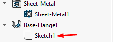
When you create a sketch in SOLIDWORKS and subsequently use it inside a feature, for example in the Extrude command, the feature swallows the sketch, meaning you cannot see the sketch directly in the feature tree. You see it inside the Extrude command.
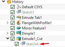
In ZW3D, there are 2 different options. If you wish, it can perform a behavior similar to SOLIDWORKS, or you can ensure that the sketch is located directly in the tree or history. When you select the sketch command, only the commands belonging to the sketch appear on the ribbon. You need to select the Exit option to confirm the command and see the other commands. When you create a sketch and confirm it, that sketch comes directly to the History area as a feature. Even if you use an extrusion command subsequently, you can see both the feature belonging to the sketch, meaning the node, and the feature that uses that sketch, for example the Extrude Tab.

If you want your sketch to be swallowed by the Feature, you need to create the sketch while inside the Feature.
After processing as shown in the GIF, you need to confirm the Sketch to be able to return from the sketch to the Extrude command. Afterwards, when you confirm the command by making your desired selections within the Extrude command, you can see in the History area that the sketch has been swallowed by the Extrude command.
SOLIDWORKS vs ZW3D, All Sheet Metal Commands Comparison
You can review the visual containing the modeling of a Sheet Metal part using both ZW3D and SOLIDWORKS below, and the commands included in the visual.
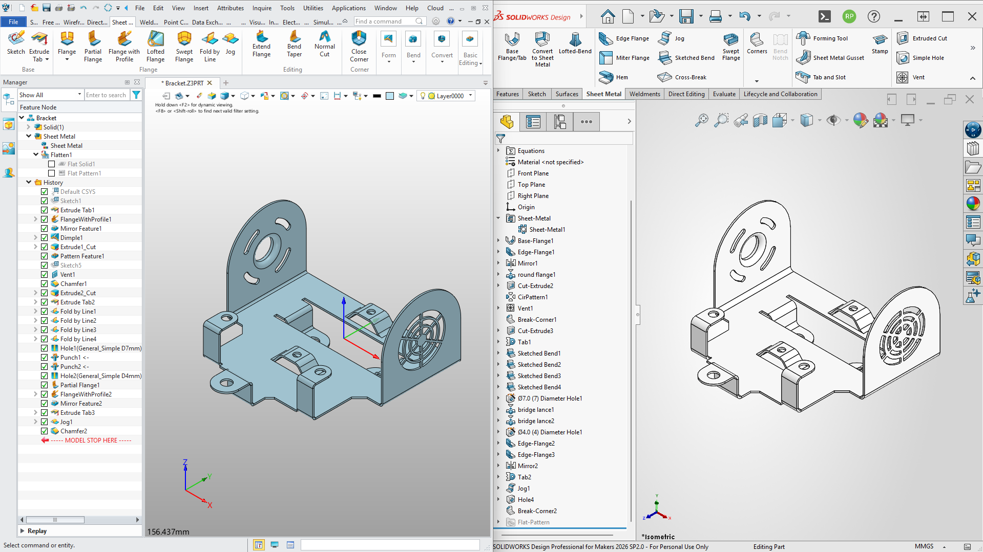
To examine in detail which sheet metal command in SOLIDWORKS corresponds to which Sheet metal command in ZW3D and what differences exist between the commands, you can review our comparison table consisting of a total of 12 sections by clicking the link below.
Sheet Metal — Complete Command Comparison
Editing Imported STEP Sheet Metal Data
As we have seen in the command comparisons in the previous section, when you manage the design process from scratch, each software has its own strengths and different approaches. However, in the manufacturing world, workflows do not always proceed by creating your own designs from scratch.
Overcoming Dumb Solid Limitations
If you not only manufacture your own designs but also prepare data coming from your customers for production, you have certainly encountered “dumb solid” (STEP, IGES, etc.) files that lack a feature tree. Companies generally prefer these formats when sharing their data to protect their intellectual property and design details. But a STEP or IGES file does not contain a design history (feature tree), it only presents you with the 3D frozen geometry of the model. You have probably experienced how time-consuming and confusing it is to edit such “dead” data.
When the subject is sheet metal, this situation goes one step further. Even if the data you receive is actually designed according to sheet metal rules, you cannot directly get a flat pattern because its format is STEP. There is also the other side of the coin, sometimes a 3D model drawn with standard solid modeling commands needs to be converted directly into a sheet metal suitable for production.
Electrical Enclosure Case Study Workflow
Exactly at such gridlock points, we will examine in detail through a Case Study what kind of workflow ZW3D offers when intervening in data without a feature tree (dumb solid).
Scenario: Your customer sent you an Electrical Enclosure design to be manufactured from sheet metal. They request you to make some dimensional changes on this design and then proceed to production. However, since they did not want to share the original CAD file due to privacy concerns, they transmitted the data to you only in STEP format. Now, let’s examine step by step how ZW3D’s ‘Direct Edit’ and Convert to Sheet Metal commands are applied in practice when responding to this customer request.
Pre-Editing Analysis and Dimensional Measurements
Pro Tip: Before making changes on a STEP data, it is useful to make some dimensional measurements on the model. For example, as shown in the video, before changing the position of the holes, you need to know whether each hole is at equal distances or different distances by measuring the distances between the referenceable surfaces and the hole center.
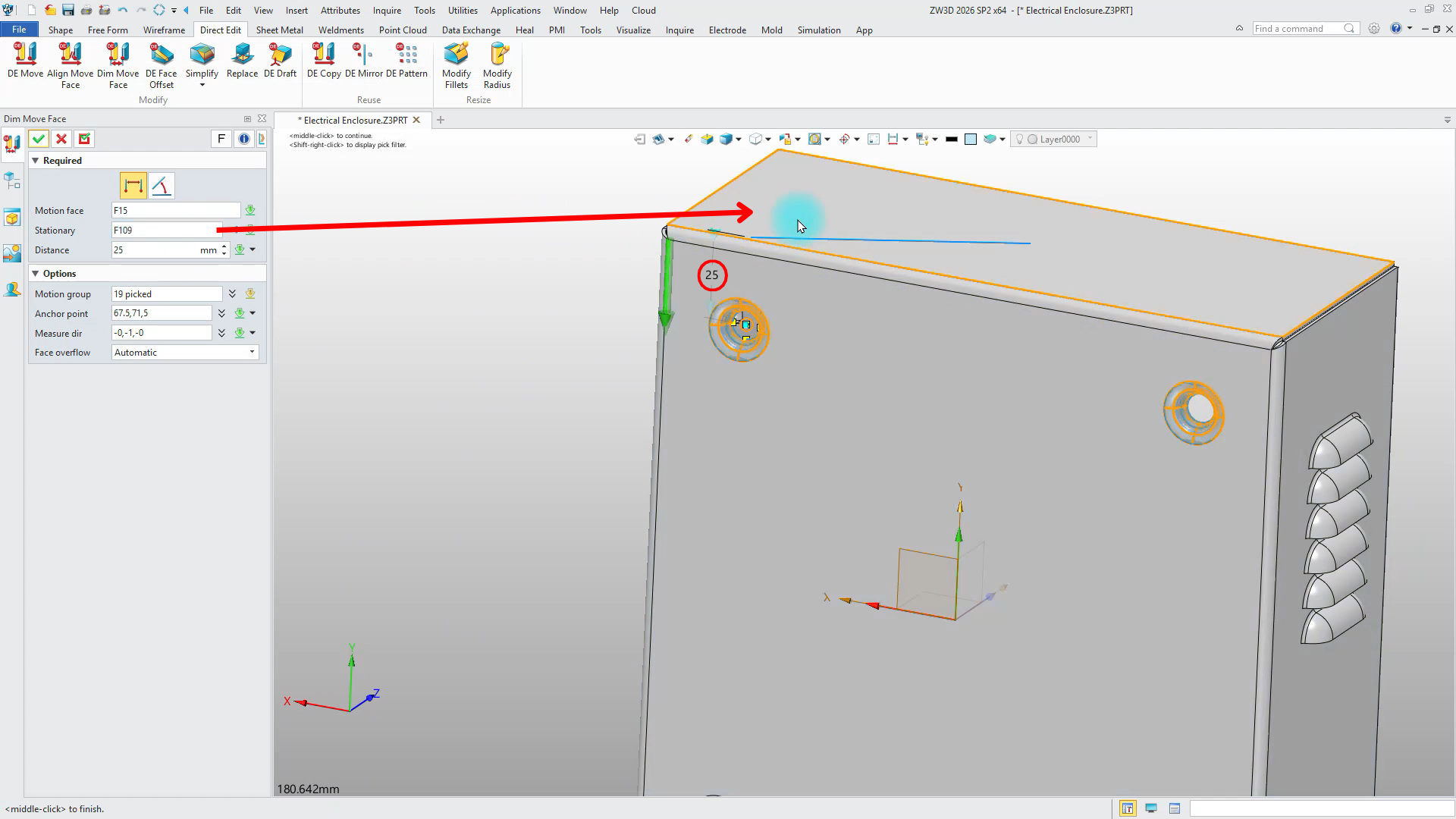
Modifying Hole Positions with Dim Move Face Command
Pro Tip: If you want to move holes, you can use the DE Move command. However, if you want to move holes by taking a specific face as a reference, you should use the Dim Move Face command. When you need to move a punch-like hole, all faces belonging to the punch must be selected. You can select multiple faces to be moved in the Motion group area located inside the Dim Move Face command.
The most important point you should pay attention to while using this command is that for the command to work, meaning to be able to move the faces, a face other than the faces selected as a group must also be selected in the Motion Face area. If you need to perform an operation like the one in the video, you need to leave one of the faces selected as a group unselected. You need to select the unselected face via the Motion Face area.
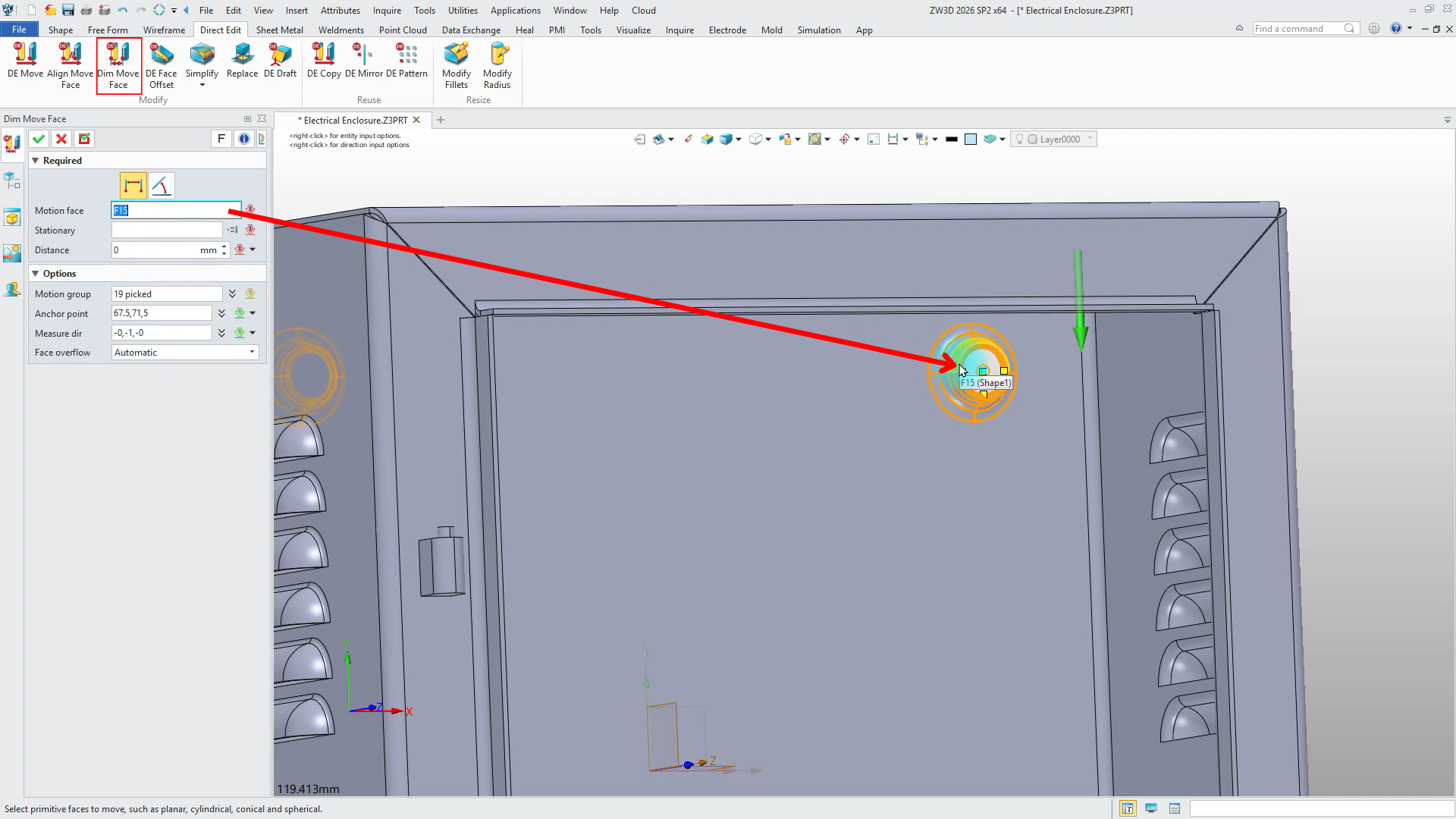
Finally, when you select the face to be referenced during moving via the Stationary area, you can also see the current distance.
Creating Linear Patterns for Punch Features
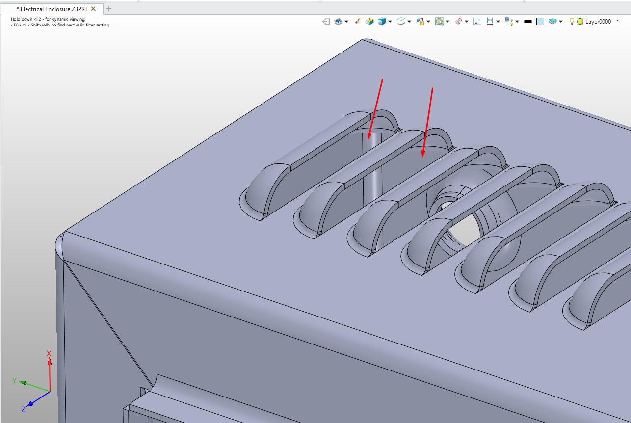
Pro Tip: When you want to make a linear pattern on your data, you can use the DE Pattern command. The most important detail you need to pay attention to when using this command is that if you want to pattern a feature such as a hole, for example a louver, in addition to selecting all faces belonging to the louver, you also need to select the faces that form the open profile area of the louver.
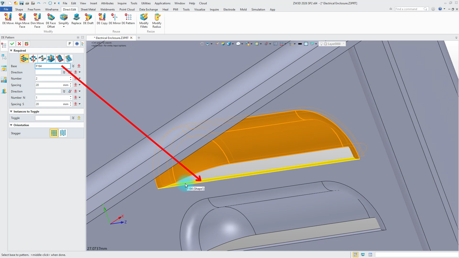
If we consider the cases where the area shown in the image above is selected and not selected:
Not Selected Case: When you examine the visual below, you can see that the surfaces indicated by the arrows are closed geometries. This is an undesirable situation for a louver.
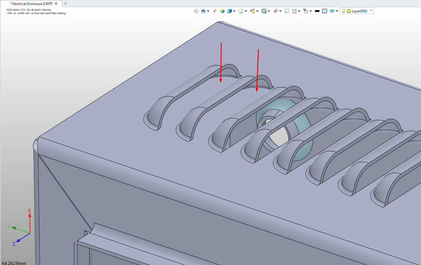
Selected Case: When you examine the visual, you can see that the louver is as it should be.
Converting Dumb Solids into Manufacturable Sheet Metal
Pro Tip: After making the necessary adjustments, you can convert your model to sheet metal with the Convert to Sheet Metal command. After selecting the stationary face from within the command, it will be sufficient to select the Collect all bend option so that all faces containing bends can be found automatically. One of the important features that distinguishes ZW3D from its competitors regarding sheet metal is that it understands punch shapes during conversion to sheet metal. If you have punch shapes in your model (Emboss, Louver, Lances, etc.), you can ensure these shapes are also included in your sheet metal model by activating the “Keep punch shape” option.
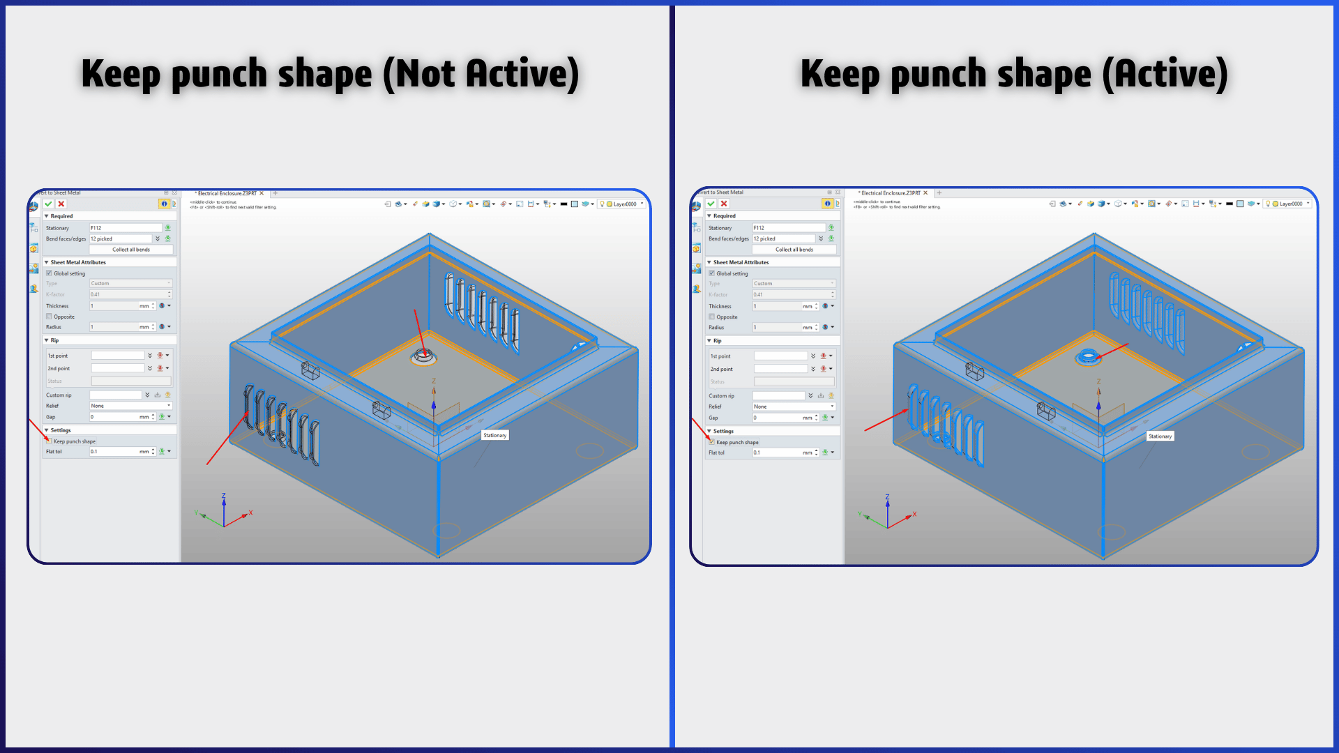
In the visual above, on the left, you can see that when “Keep punch shape” is not active, the Louver and Dimple (Emboss) shapes are in transparent color (the color of unselected items), not in blue color (the color of selected items). In the picture on the right, you can examine that with the Keep punch shape feature selected, the Louver and Dimple items are in blue, meaning they are selected, and the system can recognize these features.
Pro Tip: Inside the ZW3D Sheet Metal commands, there are also commands you can use specifically on data converted in this way. With the Extended Flange, Bend Taper, and Change Bend commands, you can make modifications on sheet metal parts that do not have a feature tree history.
Exporting Flat Patterns for Laser Cutting
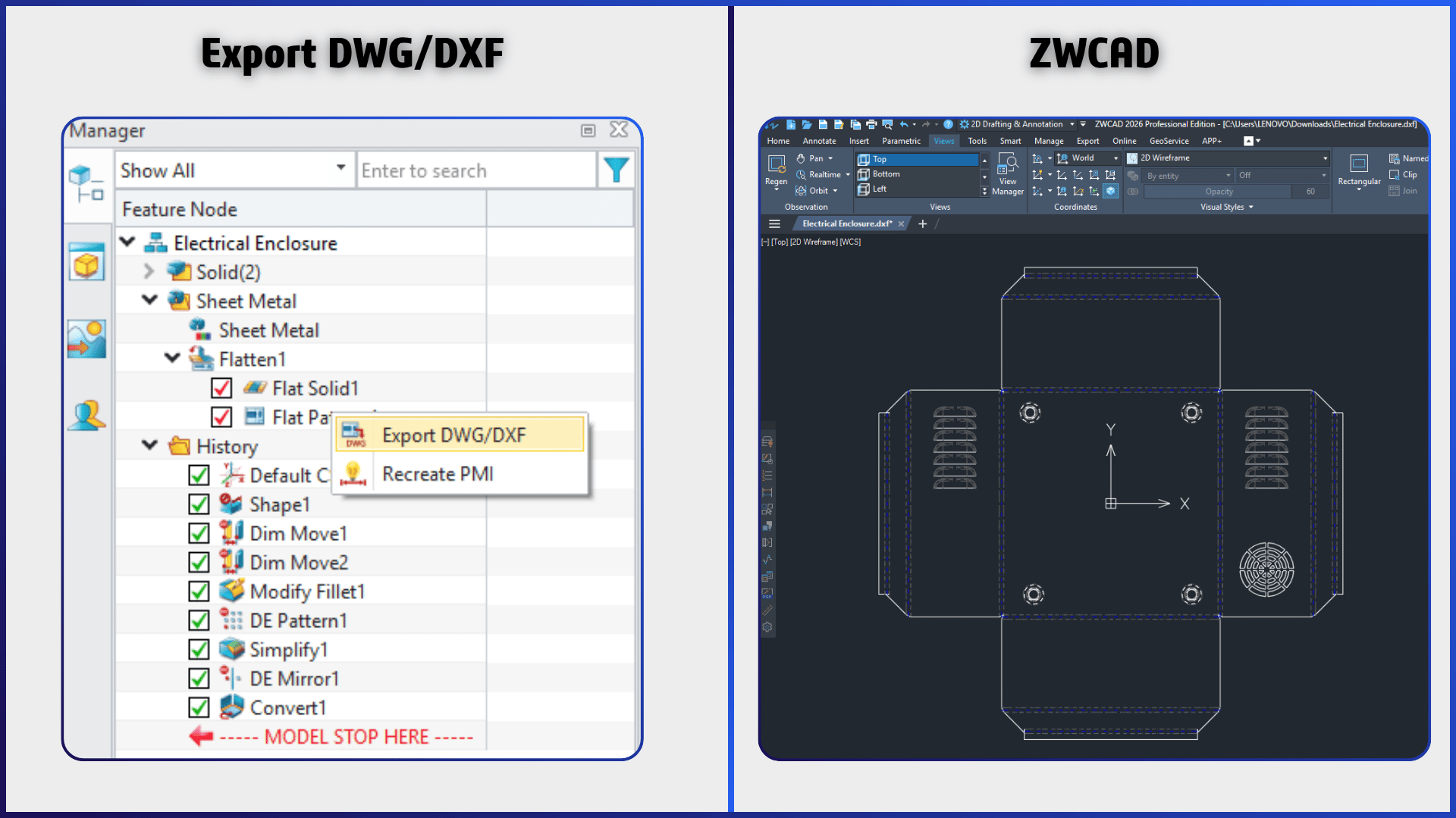
Pro Tip: You can now get the flat pattern of the model you converted to a Sheet Metal model and create DXF/DWG files for laser cutting. To be able to export a DXF/DWG file, you can right-click the Flat Pattern option inside the Flatten folder located in the History and select the Export DWG/DXF option from the opening menu.
Working with Large STEP Data
STEP data might not be small, as shown in the previous section. Although the main focus of this blog content is on Sheet Metal commands, the following question might come to the mind of the reader examining the blog post: What is its performance when working with large STEP data? How fast or slow does it open a large STEP data file compared to its competitors?
We conducted a small test to answer this question. In such tests, it is of great importance that the test conditions are the same. Both software were run on a computer with the following specifications, without any background programs running.
Lenovo ThinkPad P15 Gen 1 Mobile Workstation (Intel Xeon W-10885M 8 Cores/16 Threads, NVIDIA Quadro RTX 4000 Max-Q 8 GB VRAM, 64 GB RAM, 1.5 TB SSD)
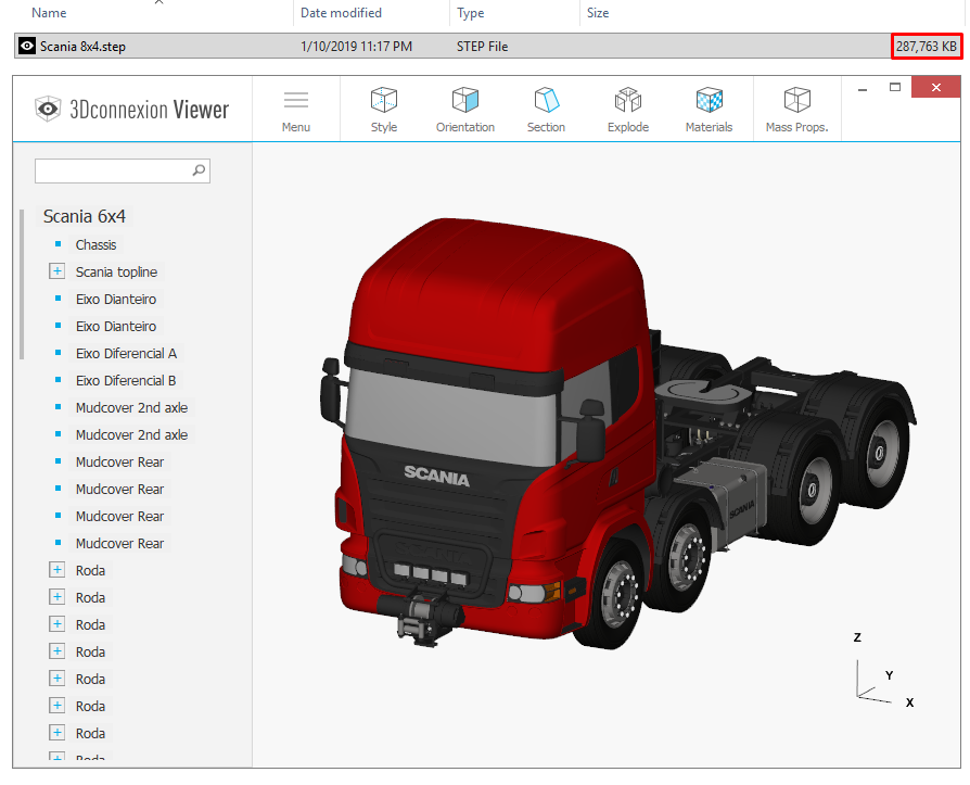
The size of the data used for the test is 287 MB.
Both software were tested using the 2026 SP2 version. The test was repeated multiple times to check if there were any differences between the resulting values. The stopwatch was stopped at the moment the model allowed the first mouse movement after loading.
SOLIDWORKS STEP Data Opening Time: 4 min 45 sec
ZW3D STEP Data Opening Time: 1 min 30 sec
Data used for the test: Scania R620 V8 8×4
Kernel Architectures
One of the main reasons for this speed difference that emerged in the tests is the processing philosophies in the kernel architectures of the software. The Parasolid kernel used by SOLIDWORKS has quite strict topological rules regarding solid modeling. While importing STEP data, it performs an intensive geometry validation and surface knitting/healing operation in the background to ensure that the model forms a completely closed (watertight) volume. The ‘Overdrive’ kernel developed by ZW3D has Solid-Surface Hybrid modeling capability.
Thanks to this flexible structure, the system does not waste time with heavy validation tests and mandatory surface knitting operations while importing the model, it loads the geometries into memory as they are and allows you to start working on ‘dumb solid’ data much faster. You can actually clearly see the flexibility provided by this hybrid kernel structure of ZW3D in the working principle of the Direct Edit tools we examined in the previous section.
Transition Process from SOLIDWORKS to ZW3D
Up to this point, we have examined ZW3D’s Sheet Metal capabilities, how it prepares external STEP data for production, and the differences between the commands in detail by comparing them with competitor software.
The Customer’s Inner Voice
“Alright, ZW3D meets our company’s technical requirements, we can purchase the software, but what will we do with our existing CAD data (legacy data) accumulated over the years? Even if Direct Edit tools work wonders on external STEP data, we must be able to see the feature tree history in our own designs and manage it when necessary. Moreover, some of our designs contain configurations, and some contain complex equations. Even if we somehow solve the part designs, how will we transfer that many assemblies and assembly mates without loss? How can we overcome these problems?”
If you have such concerns regarding the transition process, you will find the solution you are looking for in this section.
Migration with the IPX Add-in
This is exactly where the IPX add-in comes into play. The add-in allows you to convert your SOLIDWORKS data directly into ZW3D format. Along with this software that offers Part, Assembly, and Drawing support, you can transfer your design history to ZW3D. For the software to work, both SOLIDWORKS (currently, a maximum of the 2024 version is supported) and the ZW3D 2026 SP2 version must be installed on your computer at the same time.
We conducted a case study showing how IPX works over the Electrical Enclosure model we used in the previous sections. Since we will publish a separate, much more detailed blog post about the capabilities of this add-in in the future, we are only showing the basic workflow and steps here for now:
Preparing and Running IPX
Pro Tip: SOLIDWORKS and ZW3D must be installed and activated before using IPX.
Pro Tip: You can launch IPX either from within SOLIDWORKS or directly from the IPX application. If you launch IPX from SOLIDWORKS, make sure no documents are open in the SOLIDWORKS window.
Understanding the IPX Translation Process
Pro Tip: The IPX software opens the selected models via SW and examines each feature that makes up the model step by step. After the feature recognition is finished, it automatically launches the ZW3D software and saves the model by creating it step by step on ZW3D.
Pro Tip: The IPX software optionally translates the data in the forming tool libraries used in your model and saves them to the ZW3D library. Thanks to this process, if there is a forming operation on your Sheet Metal model, it performs the forming operation using that data in the library.
Evaluating Conversion Results
Pro Tip: When the operations are completed, the ZW3D software closes automatically. The IPX software notifies you. It also informs you about the conversion quality of the converted parts on the software screen (such as Excellent, Average).
Pro Tip: The software brings limitations along with its functionality. It may not be able to translate all commands. You can request the documentation regarding which commands it can translate from the ZW3D Team.
Co-Founder at ChampionXperience
Ridvan Polat is a SOLIDWORKS Elite Application Engineer, Founder of ChampionXperience, and a recognized SOLIDWORKS, ENOVIA, and 3DEXPERIENCE Champion. He specializes in CATIA & ENOVIA technical support and 3DEXPERIENCE early engagement adaptation, helping organizations optimize PLM workflows.
Latest posts by Rıdvan Polat (see all)
Subscribe
0 Comments
Oldest
