Transitioning from one CAD software to another is generally a painful process. For companies, being able to access the feature tree history of designs and make modifications when necessary is of critical importance. Despite these challenges, the primary reasons for switching platforms are usually cost, performance, and accessibility needs.
As content creators, we actively use many professional CAD programs. In this blog post, we share step by step how we migrated our three-wheeled car (GoBuggy) project, which we brought to life with a “Maker” philosophy, from the SOLIDWORKS xDesign (formerly SolidWorks Cloud) ecosystem to Onshape.

After 4 years, we decided to redevelop our vehicle named GoBuggy, which we produced in 2022. Along with this rebuild process, we also aimed to transfer the design to a different CAD environment. In our article, you will find our experience of transferring GoBuggy, which first we modeled using browser-based cloud applications (xApps) such as xDesign, xFrame, xSheetMetal, and xShape, to the Onshape platform.
(Note: We will not cover the manufacturing and design details of our GoBuggy vehicle in this article. Those who are curious can check out our related blog post.)
We will examine this migration process under the following 5 main topics:
- Data Architecture
- Command Differences
- Assembly Logic
- Data Management
- Performance
Since it is a detailed process, we decided to present the blog post in two parts. In this section, we will examine File Structure and Command Differences.
While making this comparison, instead of proving the superiority of one software over another, I focused on practical and objective information that will facilitate your transition process.
Data Architecture and Infrastructure Differences
The most prominent distinction between the two platforms emerges in their cloud data storage and file architecture logic. Although both ecosystems are entirely browser-based (cloud) structures, the ways they handle data are quite different.
SOLIDWORKS xDesign (3DEXPERIENCE) Data Structure
Every part or assembly you create in SOLIDWORKS xDesign and other xApps is saved in a cloud storage area called a Collaborative Space. The system assigns a unique ID to each design and stores it as a Physical Product object.
- Bookmark Editor: A Collaborative Space does not operate on traditional folder logic. To organize your designs and manage access permissions, you use the Bookmark Editor.
- 3DXML Format: In the background, all xApps data is stored in the .3dxml format. Unlike traditional CAD formats, when you want to export a large assembly consisting of hundreds of parts, the system combines and delivers all components within a single, compact file.
- Widget (Application) Based Ecosystem: The SOLIDWORKS xDesign ecosystem consists of purpose-built, specialized modules (widgets). You use xDesign for parametric design, xSheetMetal for sheet metal, xFrame for structural frame design, xDrawing for technical drawings, xMold for mold design, and xShape for organic surface modeling. Switching between these modules is possible, and design and assembly are carried out within the same environment.
Onshape Document Structure
Onshape, on the other hand, offers a document-centric system instead of a classic file- or object-based structure. When you start a new project in Onshape, a solid modeling workspace (Part Studio) and an assembly workspace (Assembly) are automatically generated as tabs within a single document.
- Integrated Workspace: You can manage all engineering processes such as design, assembly, technical drawings, rendering, and CAM under the same document umbrella across different tabs.
- Folders: Documents are organized by creating folders within the storage interface.
- Permissions: User permission levels are defined dynamically on a document or project basis. Thanks to role-oriented permission levels such as View, Comment, Edit, and Share, team members and external suppliers can safely collaborate in the same cloud environment with different access rights.
Differences Between Commands
The tools we used most intensively throughout the project were the Frame and Sheet Metal commands. Due to the depth of the topic, instead of squeezing all the details of the transition process into a single article, we will focus only on the differences in the Frame commands in this section.
Structural Member Commands
When designing the chassis of the vehicle, we decided to use T-slot aluminum profiles (Sigma profiles). You can check out our related blog post to review the reasons behind this choice and the details of our decision.
Adding Custom Profiles to the Library
The T-slot profiles we were going to use in the design were outside the standard dimensions. Therefore, we had to manually add the “30×30 Heavy T-Slot Profile” to the system library where Frame profiles are located.
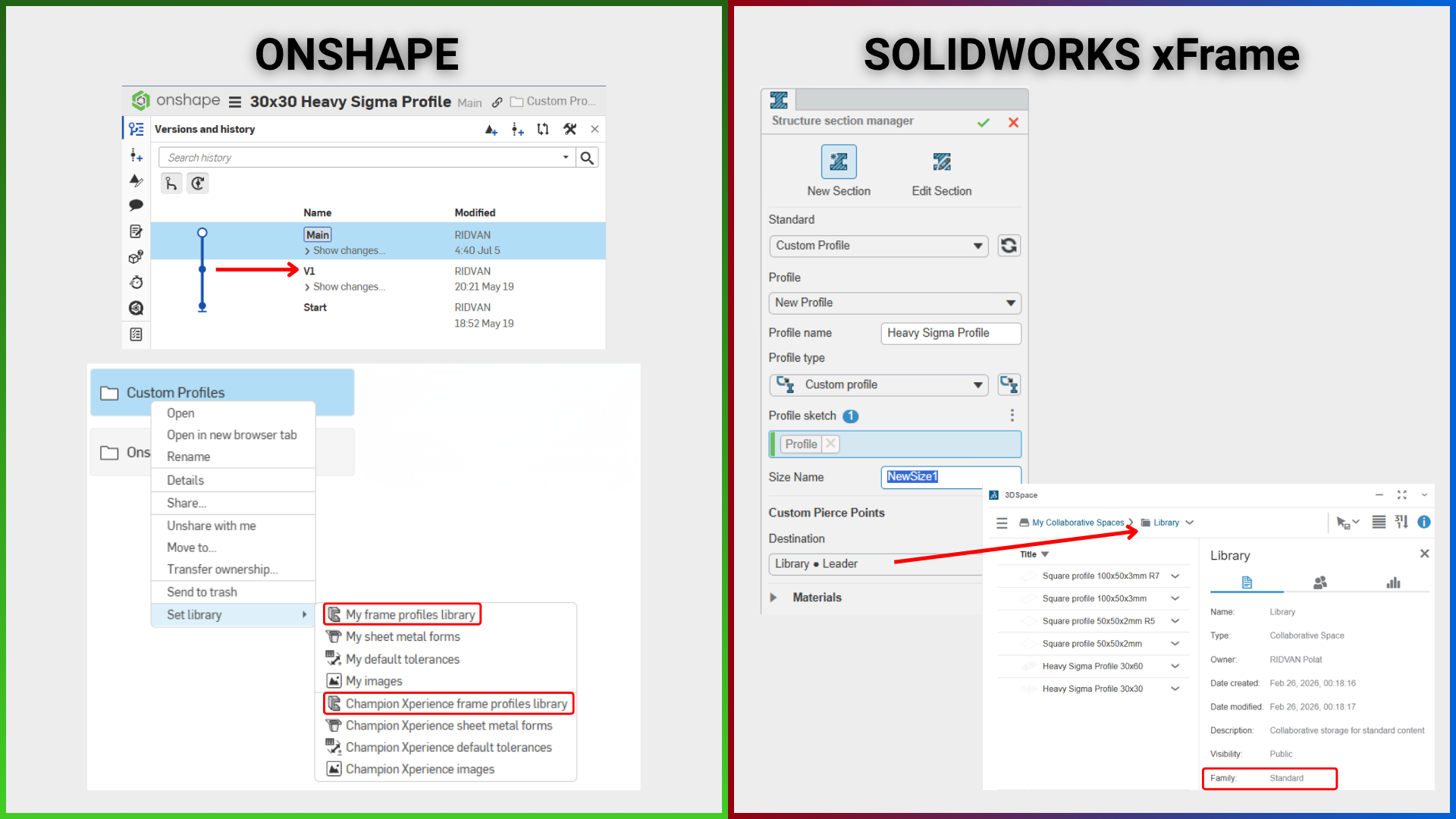
It is possible to create custom profile libraries on both SOLIDWORKS xFrame and Onshape. I have detailed the main similarities and differences between the two platforms below.
In-House Shared Library Management
Library management and data storage logic differ in the two software as follows:
- SOLIDWORKS xFrame: Materials, drawing templates, and structural member profile sketches are stored in separate “Spaces” (collaborative workspaces) on the 3DEXPERIENCE platform. To add a new profile, you must have access permissions and editing authority for these areas. The system provides control entirely through these customized data areas (Spaces).
- Onshape: You can either create your own personal library or set up a shared library that you can share with your teammates. You need to have administrator (admin) privileges to open a shared library company-wide.
Data Security and Flexibility
The points where the two programs diverge in terms of protecting profile designs and ease of use are as follows:
- Versioning and Security: In Onshape, documents converted into a library folder and hosting profile sketches must be saved as a “new version” to be listed in the Frame menu. This logic corresponds to the “Read-Only” state in traditional PDM (Product Data Management) systems and prevents profile sketches in the library from being accidentally modified. In SOLIDWORKS xFrame, since the sketches added to the library are added to the Space area as a Structure Section type, any change you make on the sketch only affects the Physical Product object type.
- Flexibility: Both SOLIDWORKS xFrame and Onshape include standard profile libraries. In SOLIDWORKS xFrame, you can only use profiles that have been officially registered in the library beforehand. On the Onshape side, even if you do not add it to the library, you can directly use a sketch you drew in any document as a profile.
Metadata
Onshape: You can add metadata to the profile to be added to the library using the Tag command. You can see this information when you create a Cut list. For example, we added “Supplier” information for the 30×30 Heavy T-Slot Profile. Furthermore, if you have a profile with changing dimensions, you can add this into the Tag command to ensure that the selected dimension or configuration information in the profile dynamically appears in the Cut list (changing according to the selected configuration).
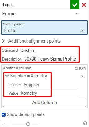
SOLIDWORKS xFrame: There is no corresponding command for this.
Configurations
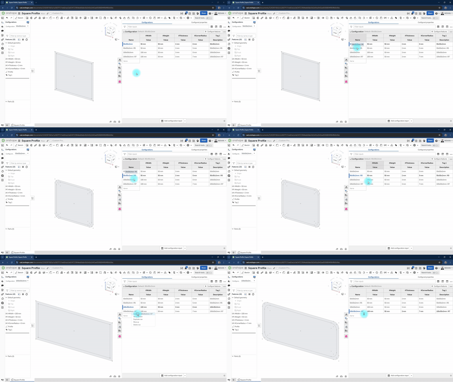
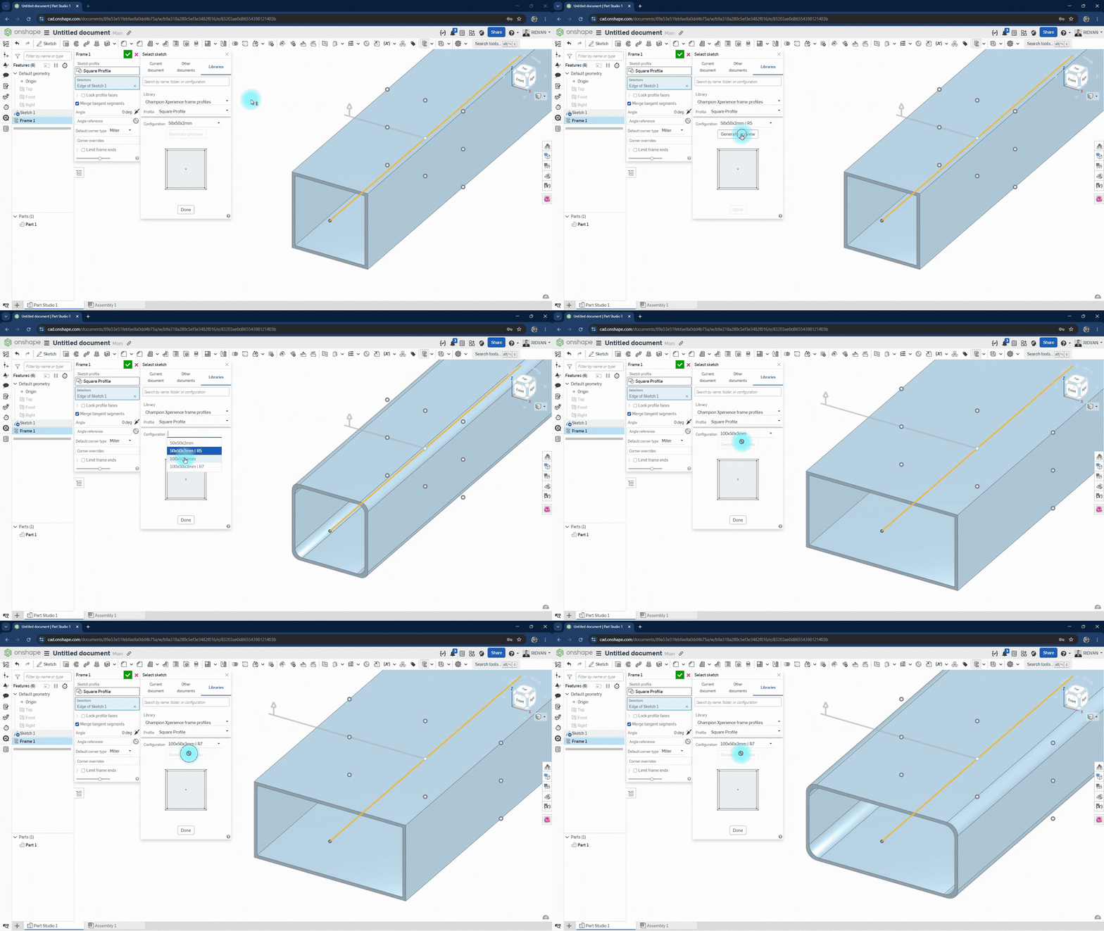
Both softwares have the feature to add different sizes of profiles.
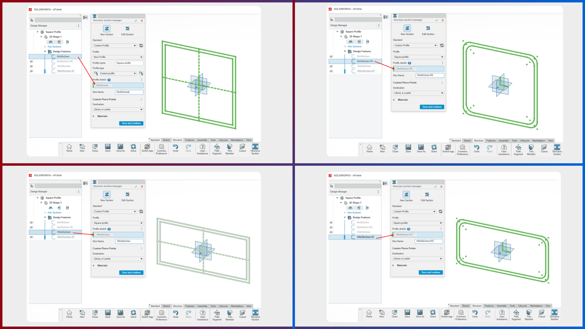
- SOLIDWORKS xFrame: To use this feature, you must have more than one sketch within the Component, or you must add new sizes into the same library by creating different components. However, modifications made later to the sketch added to the library do not affect the profile in the library. This is because, as I explained earlier, the profile object type in the library is not a Physical Product but a Structure Section, and there is no method to directly synchronize this change to the library.
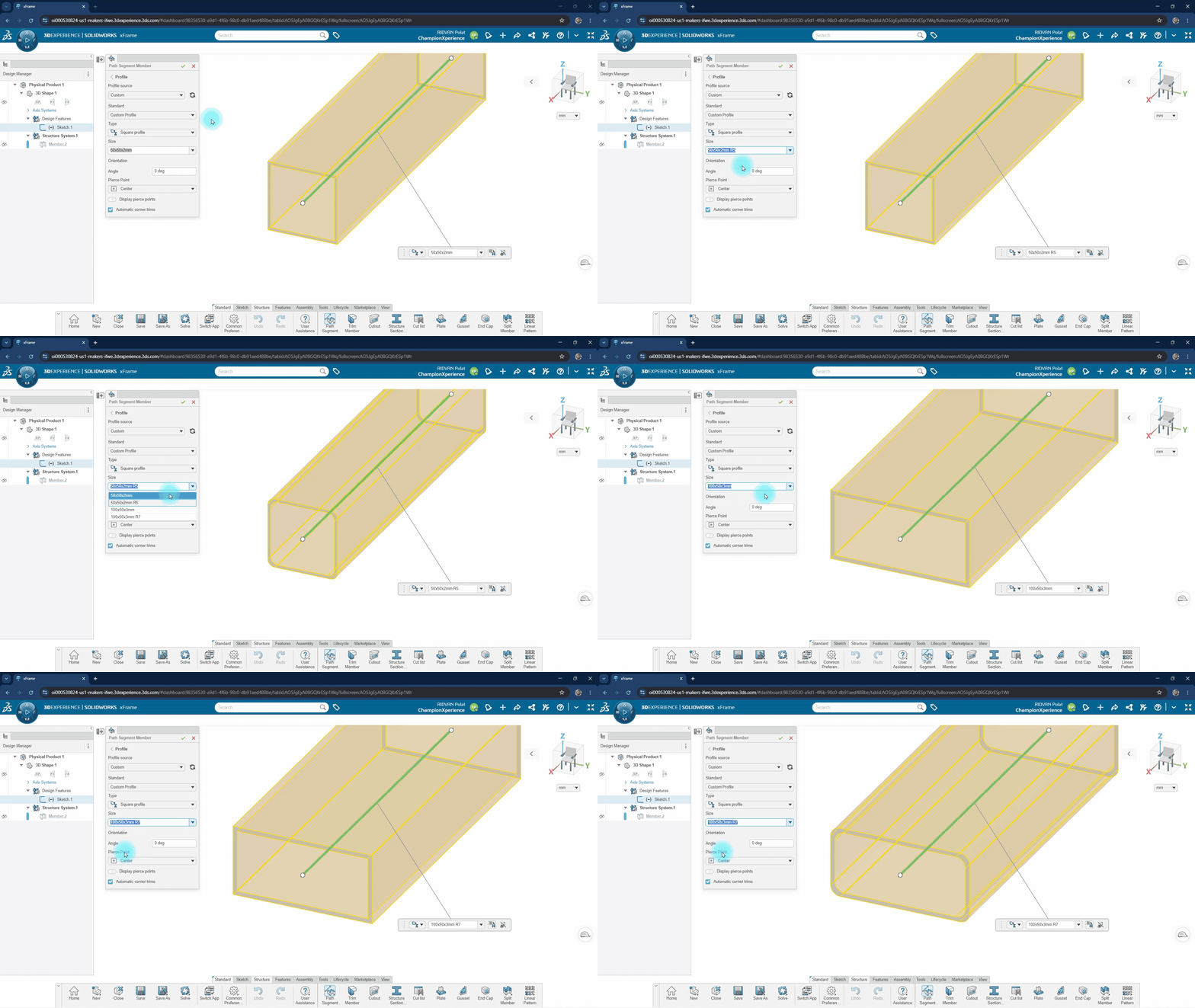
- Onshape: You can configure a single sketch to represent multiple profile sizes using configurations, eliminating the need to create separate sketches or components for each size. When the sketch is updated and a new version is created, existing models are not automatically affected. Instead, you can choose when to update the referenced version, allowing you to bring the latest profile changes into your models whenever you’re ready.
Sketching Commands
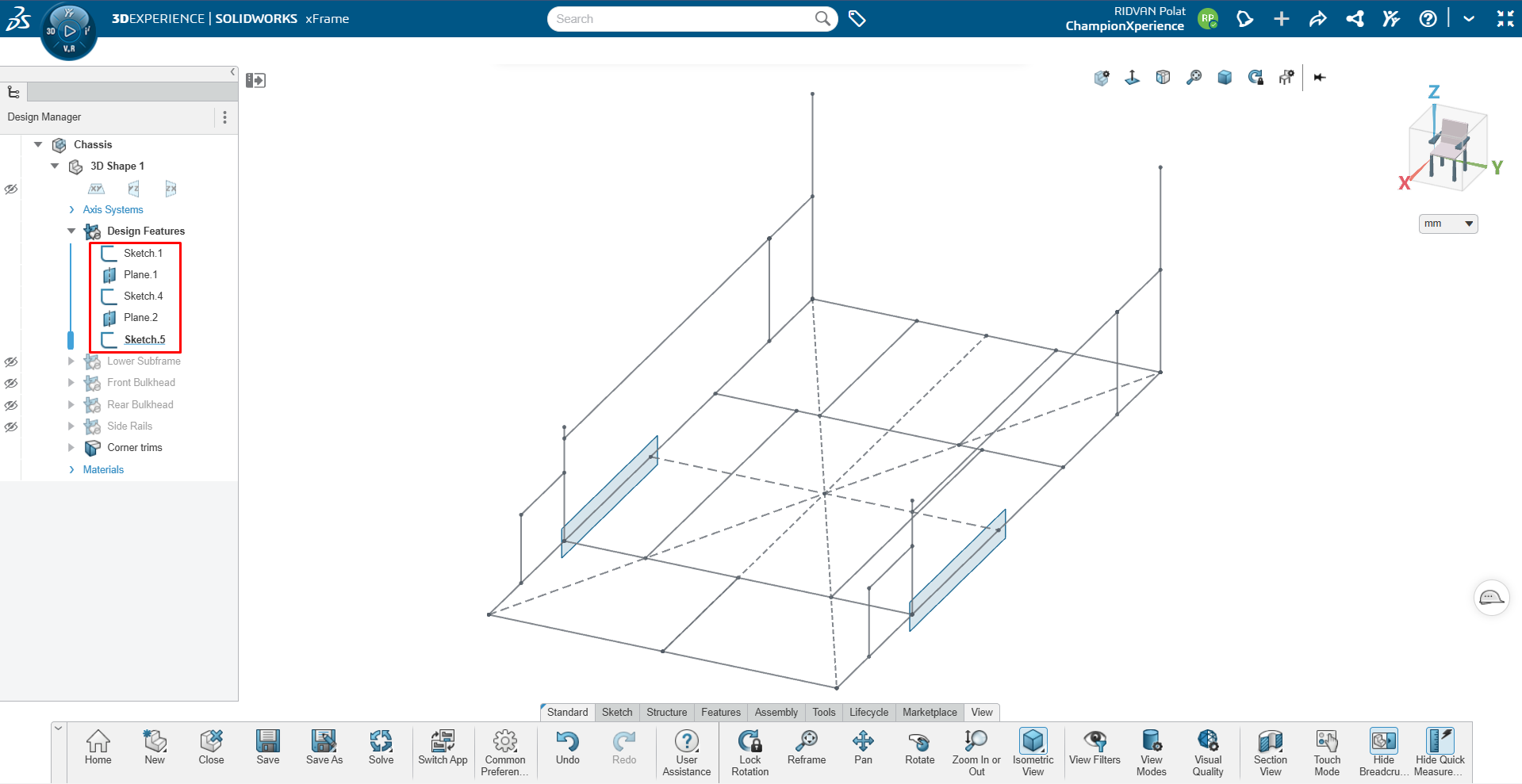
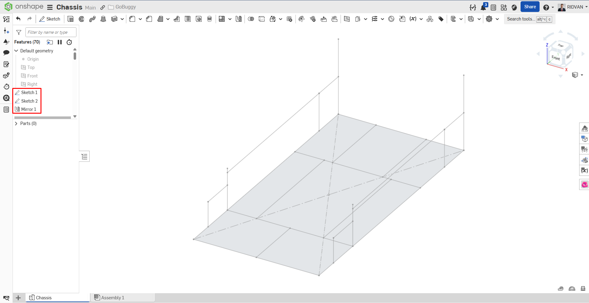
While creating the chassis of the car, we needed to create 2D geometries. Additionally, to form the Front Bulkhead, Side Rail, and Rear Bulkhead sections on the chassis, the sketch geometry needs to be in both directions.
- SOLIDWORKS xFrame: We created the chassis geometries with the help of planes. The way to transfer the created sketch geometry symmetrically to the other direction is to create a plane and convert the existing geometry with the Convert Entities command.
- Onshape: There is a similar workflow, but differently, there is the Mate Connector command, which allows you to sketch directly on the coordinate points on the line you select without entering the plane command. In Onshape, you can directly mirror the sketch geometry to the other direction with the Mirror command by selecting a plane, just like in 3D geometry.
Frame Commands
Although the general operating logic of Structural Members (Frames) is similar in both softwares, there are workflow differences between them.
- SOLIDWORKS xFrame: There are many options for creating a structural member. For example, you can create a profile with a line, through the intersections of surfaces with reference planes, by taking the space between two previously created structural members as a reference, or directly with point-based selections.
- Onshape: There is a single command for creating structural members. This command detects your selections, allowing you to create structural members with a line or a point-to-point closed geometry selection.
- Common and Different Commands: Both softwares include frame-specific options such as Trim, Gusset, End Cap, and Cut List. In addition to these, SOLIDWORKS xFrame also has frame Cutout, Plate, Split, and Merge Member options. In Onshape, options within the solid modeling commands provide similar functions corresponding to these commands.
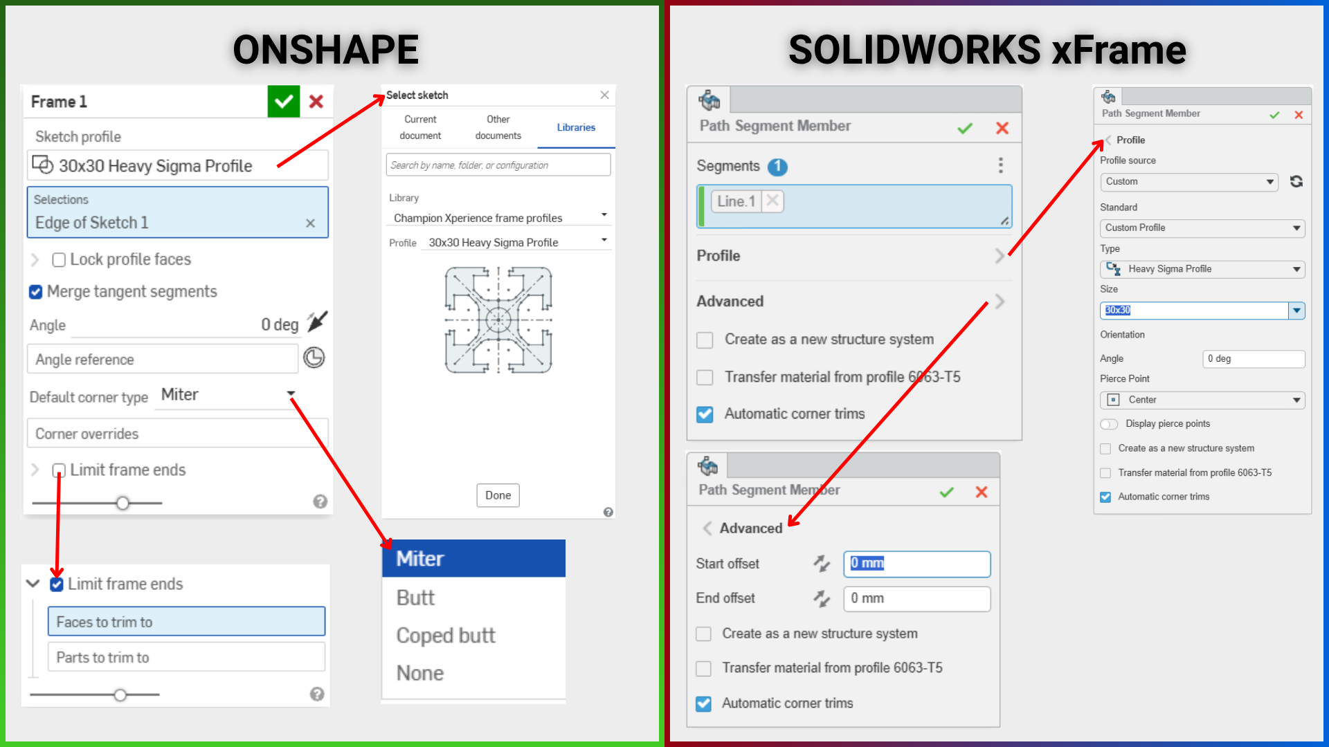
- SOLIDWORKS xFrame Command Window: When the Path Segment Member command (a command to create a structural member) is selected, there is an area where you can select sketch geometries, an area where you can select profile shape, size, and orientation, an area where you can adjust start and end offset, and an area that performs automatic corner trims.
- Onshape Frame Command Window: It includes an area where you can select profile shape and size, an area for orientation, a Corner Type option, a Corner overrides option, and a Limit end frame option.
Feature Tree and Component Management
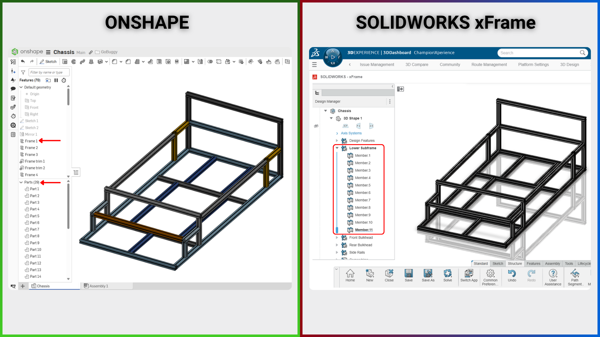
- SOLIDWORKS xFrame Feature Management: When the command is approved after geometry selection, a feature of the Ordered Geometrical Set (Structure System) type is added to the Design Manager area. This Structure System gathers all structural members under it. If you want to make any changes and it is a change that should affect all members, you can edit the Structure System, or if it is a change related to only a single structural member, you can edit that member.
- Onshape Feature Management: When the command is approved after geometry selection, a feature named Frame is added to the Feature List area. However many structural members were created inside the Frame feature, that same number of members is added to the Part List area. Editing is done through the Frame feature.
Corner Trim Logic
- SOLIDWORKS xFrame Corner Trims: While in the Path Segment Member command, if you approve the command with the Automatic Corner Trims option selected, the trimming operation is done automatically, and you can see the trimmed items under a feature called Corner Trim in the Design Manager. The Auto Corner Trims option also automatically makes the corner type selection. You can change the corner type selection by editing the Corner Trims feature.
- Onshape Corner Trims: When you select an end-to-end connected sketch geometry and approve the command, the cutting operation between the corners is done automatically. Additionally, Onshape allows you to select the corner type while in the Frame command. If you want to add a structural member between two opposite profiles, the cutting operation is not performed automatically. With the Limit frame end option located in the command, you can limit the dimensions of the structural member by selecting either a surface or a body.
Corner Type and Direction
- SOLIDWORKS xFrame Corner Type and Direction: There is no option that allows you to select the corner type (such as Miter, Butt) while in the Path Segment Member command. For this, you need to edit the Corner Trim option added to the Design Manager. You can adjust the direction of the structural member during this editing process.
- Onshape Corner Type and Direction: When in the Frame command, you can both determine the corner type and adjust the direction of the structural member by selecting a corner point with the Corner Overrides option.
Cut List
Both softwares have the Cut List creation feature, which is of critical importance for manufacturing.
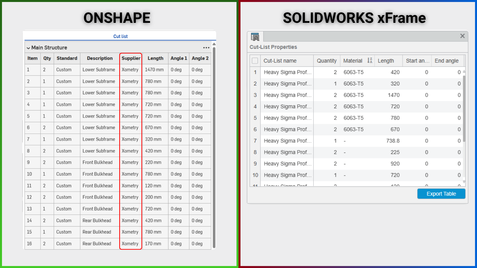
- SOLIDWORKS xFrame: In the cut list table, the name of the profile used, quantity, length, and angle values, as well as the material name if a material is assigned to the profile, are included. You can export this obtained table directly in CSV format if needed.
- Onshape: The cut list command works with a different workflow compared to SOLIDWORKS xFrame. Inside the command window, if you wish, you can select all profiles in the design to create a single cut list. In the table, unlike quantity, length, and angle values, you can also see the metadata included in the Frame library and defined with the Tag command. For example, since we added the supplier information into the “Tag” parameters of the 30×30 Heavy T-Slot Profile we used in our project, the text “Xometry” is dynamically listed under the Supplier column in the Cut List table. Also, you can transfer the generated Cut List table directly to your Excel spreadsheet by copying it with the “Copy Table” option.
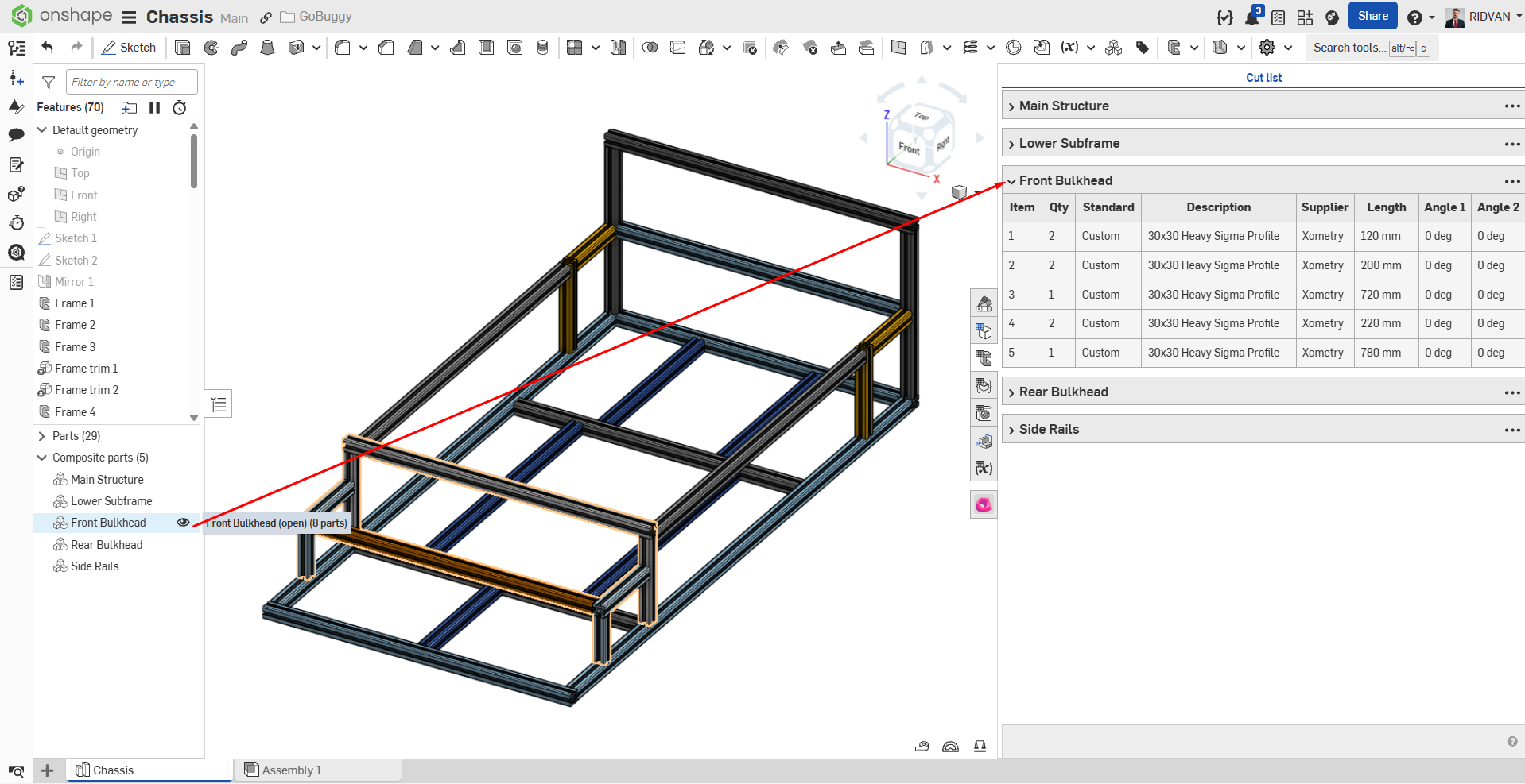
- Onshape Customization and Grouping Options: As another customization option, while in the Cut List command, we can group the structural members forming the chassis among themselves. For example, we can divide the car chassis into 4 different groups as Lower Subframe, Front Bulkhead, Rear Bulkhead, and Side Rails, and show this distinction in the cut list. Furthermore, each cut list you create by dividing into groups is automatically added to the Composite Parts area in the model tree (Composite Part is a feature in Onshape that combines multiple bodies to act as a single part).
- Onshape Material Management: In Onshape, material information is pulled directly through the BOM Table (Bill of Materials) interface, not over the Cut List.
What’s Next?
In the second part of this series, we’ll take a closer look at the differences in assembly logic, data management, and performance between the two software platforms. If you’re considering switching to Onshape, you can try Onshape Pro free for six months using the link below.
6 Months Free Access to Onshape Professional
Ridvan Polat is a SOLIDWORKS Elite Application Engineer, Founder of ChampionXperience, and a recognized SOLIDWORKS, ENOVIA, and 3DEXPERIENCE Champion. He specializes in CATIA & ENOVIA technical support and 3DEXPERIENCE early engagement adaptation, helping organizations optimize PLM workflows.
Latest posts by Rıdvan Polat
(see all)


[…] this continuation of the series, we focus on the GoBuggy project, which we migrated from SOLIDWORKS xDesign to Onshape. In this […]