
© 2023 Created by blog.championxperience.com
There’s more than one way to design. Instead of taking a shortcut, we sometimes go the long way around, using the methods we’re most comfortable with. But when things get complicated, we start looking for the fastest and simplest path.
When you’re wrestling with a complex technical drawing or a step file that you need to create a mold for, and you’re feeling ready to throw in the towel, MultiBodies come to the rescue! In this blog post, we’ll talk about the advantages of the MultiBody commands offered by 3DEXPERIENCE Catia.

What Is a MultiBody? Why Do We Need It?
Whether you use Catia, SolidWorks, or a different CAD program, you’ve probably encountered the term “MultiBody.” The moment you transition your design from 2D to 3D, you create a single body. As you add new things to your design, this body keeps getting updated. That is, until you decide you don’t want a new 3D design to be added to the existing body—that’s when a new body appears.
So, why would you need a new body? There could be many reasons. For example:
- If you’re designing by referencing other parts, a multibody approach is a great option. Then you can separate the bodies and use them as individual parts in your assembly.
- Companies may share designs in a step or other format for confidentiality and ask you to create a mold from them. MultiBody is a great option for these situations.
- If you have a complex technical drawing, you can design each view as a separate body and then arrive at the final 3D model at the end of the day.
The list could go on! You can help us grow the list by sharing in the comments what CAD program you use and what you use MultiBody for.
How to Create a New Body
To create a new body in 3DEXPERIENCE Catia, you need to be in the Part Design environment (when 3D Shape is active). Right-click on the 3D Shape in the tree, hover over 3D Shape Object in the menu that appears, and then click on Body in the sub-menu.
The most important thing to remember when working with multiple bodies is to make sure you’re working on the right one. If you worked with the wrong body active, I’m sorry to say, but many of the features you made will be for nothing. While drag-and-drop sometimes works from one body to another, it’s best to be sure. Right-click on the body you want to work on and select Define Work in Object. When you make this selection, the name of the active body will be underlined. This is how you know which body is active.
Creating a New Body in 3DEXPERIENCE CATIA
Boolean Operations
Boolean operations perform a desired action between two bodies. We’ll dive into the details with examples, but first, a critical point to consider with Boolean Operations is to decide from the start which body will be your default. In Catia, your default body when you open a new 3D part is the PartBody. If you want to remove a cylinder from a block, the features that create the block must be in the PartBody, and the features that create the cylinder must be in a new body. Why? Because Catia doesn’t allow you to delete the PartBody—in fact, if you try, you’ll get a warning like in the image.
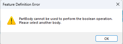
Features Definition Error MSG
In the block and cylinder example, imagine deleting the cylinder body and removing material from the block. To do the opposite, place the cylinder features in the PartBody and create a new body for the block features.
Here are the different operations:

- Intersect: Creates a new body based on the common faces of two intersecting bodies.
- Remove: Subtracts one body from another.
- Add: Combines two selected bodies into a single body.
- Assemble: Assemble is a kind of automated version of the Add and Remove commands. Let’s say you created a new body and activated it to make a 2D design. If your purpose in creating this body was to remove it from something else, you could pocket the drawing to create a solid instead of padding it. Yes, you heard that right, you can create a solid with a Pocket command. This is exactly where Assemble comes in. It looks at the main feature inside the selected body and performs the operation based on the feature’s property—if it’s a Pad, it will Add it; if it’s a Pocket, it will Remove it.
Now, let’s look at some examples of Boolean operation commands.
Complex Technical Drawings? Not a Problem with MultiBody!
You might have a technical drawing like the one below and not know where to start. (Don’t get stuck on this; it’s just an example, and for some of you, it may be a very easy one! 🙂 )
Or maybe you want to design a part to sit on a machine component, and you only have the step data of the machine component and the parts that need to be placed on it. You need to find a common intersection, but it’s complex and time-consuming. In this case, multibody gives you the flexibility to minimize the complexity.
Let’s watch how the 3 different bodies created according to the views in the technical drawing are transformed into a final 3D model with Boolean Operations.
Which Body from Which Body? Don’t Worry, Let Assemble Decide!
Working with MultiBody makes things easier. However, after a certain number of bodies, you might get confused about which body to Remove and which to Add.
When creating initial designs, choosing between the Pad and Pocket features simplifies Boolean operations. Assemble decides the operation based on the feature’s property.
If the body in the Assemble field is a Pad and the body in the To field is a Pocket, Assemble removes the Pad from the Pocket. In the opposite case, it removes the Pocket from the Pad.
In short, with a Pad and a Pocket, the body in the To field is preserved. The body in the Assemble field is removed. If both bodies are Pads or both are Pockets, Assemble treats this as an Add.
How? Let’s examine an example together.
I’ve a Step File, I Need to Create a Mold. But How? Not a Problem, MultiBody Will Handle It!
Your customer sent a “dumb solid” file like a STEP or IGES. You want to use it to create a mold and produce a part. It could be a STEP file meant to protect design confidentiality, or a scanned STL of a real product.
You’ve scaled the data for material shrinkage, but you don’t know how to create a female mold (cavity). This is where the Remove feature in MultiBody helps. It allows you to create a female mold (cavity) or a male mold (core), depending on your model.
Let’s watch as we create a female mold of a STEP-file shaft in its simplest form.
Co-Founder at ChampionXperience
Ridvan Polat is a SOLIDWORKS Elite Application Engineer, Founder of ChampionXperience, and a recognized SOLIDWORKS, ENOVIA, and 3DEXPERIENCE Champion. He specializes in CATIA & ENOVIA technical support and 3DEXPERIENCE early engagement adaptation, helping organizations optimize PLM workflows.
Latest posts by Rıdvan Polat (see all)
Subscribe
0 Comments
Oldest
