
© 2023 Created by blog.championxperience.com
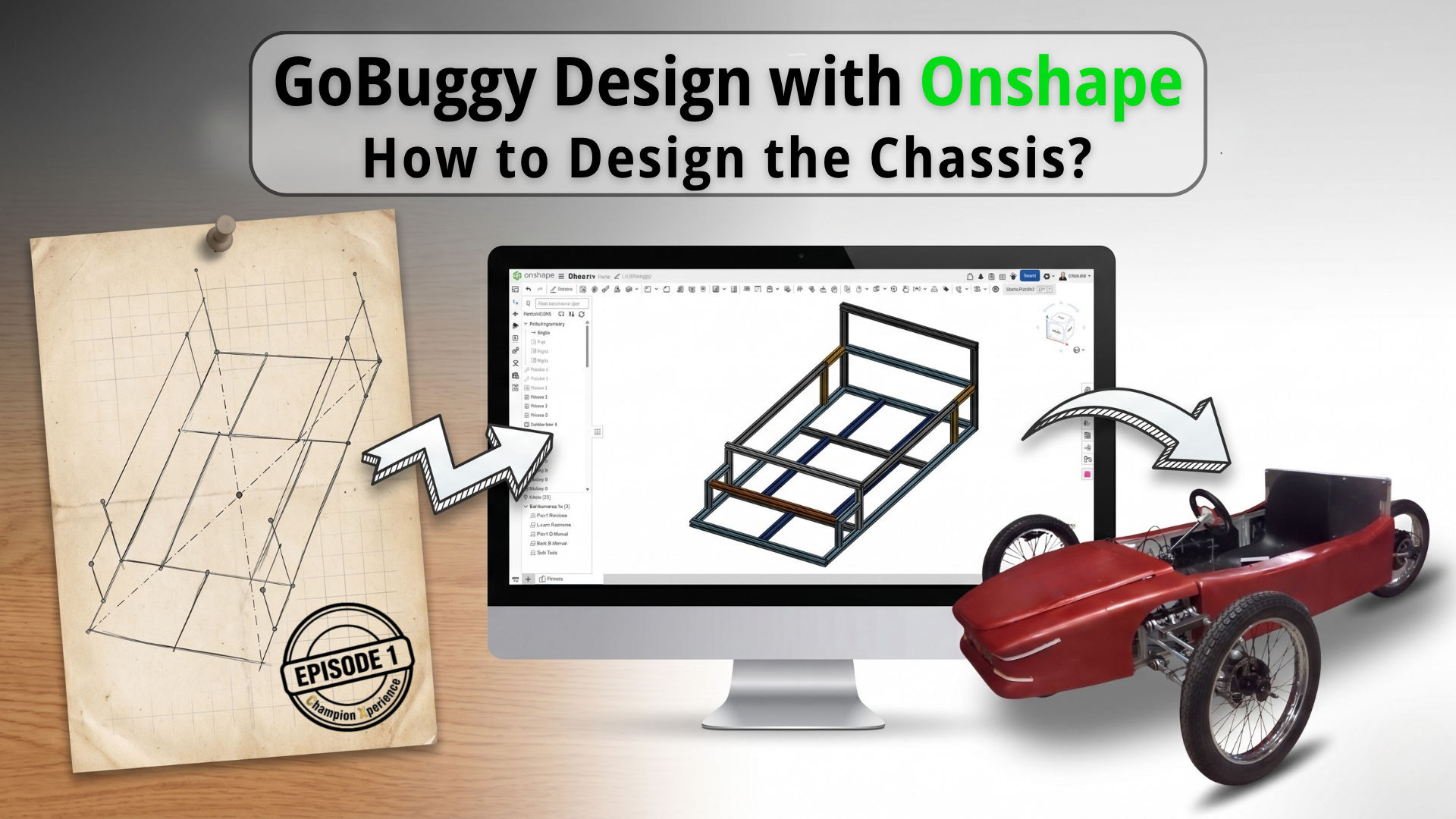
We are thrilled to start a new project. In this project, we will go through all the stages of a 3-wheeled electric car (GoBuggy) from design to production, step by step, together using Onshape, PTC’s cloud-native CAD and PDM platform. Each stage of the project will be presented as a separate blog post, allowing you to follow along step by step and see how a real-world product evolves from an idea into a manufacturable vehicle.
Before starting your own project, if you haven’t yet tried Onshape, you can create a free account or try Onshape Professional—which includes advanced tools such as Simulation, CAM and Render Studio—free for 6 months using the link below.
6 Months Free Access to Onshape Professional
The Story Behind the Project
Year 2021
The project dates back to 2021. It began with a question: Can I build a car for myself? Can I make the outer body of the car with a 3D printer? And can I build this car at home by keeping it as simple as possible, without complex parts? Can I present the entire project as open source, covering the whole process for maker enthusiasts?
The car was going to be as low to the ground as a go-kart, but it needed to have a suspension system that did not compromise rider comfort. This idea brought about a 3-wheeled hybrid car, a mix of a go-kart and a buggy, which is how the name GoBuggy was born.
Year 2022
In 2022, four friends and I designed and manufactured the project in a short period of two and a half months. However, it had some shortcomings and I wanted to improve them. I just did not have the opportunity back then.
Year 2026
I asked myself another question. 😊
Can I build a car for us? Can I build a car that my wife and I can use together?
To make this dream a reality, we migrated the entire project from SOLIDWORKS to Onshape. (I will also create a separate blog post about the migration process.)
First, I want to show you how we built the current design step by step through this series. Afterward, we will revise the design and bring a two-seater GoBuggy vehicle to life together.
What Awaits You in this Series?
Throughout the series, we will examine the different stages of the modern product development workflow, including design, analysis, assembly, production preparation, data management, and revision processes, in detail through a real-life project.
Project Architecture and Document Structure
Project architecture can often be overlooked when starting a project. When you skip this seemingly simple step and the project progresses, things can get complicated once you start working with versions, branches, and revisions.
To eliminate this complexity, it is beneficial to define the Project Architecture and Document Structure right at the beginning of the project.
Understanding Onshape’s Document-Centric System
Before defining it, it helps to understand Onshape’s system. Onshape does not operate on a model-centric basis, it operates on a document-centric basis. A document houses all your parts, assemblies, technical drawings, simulation studies, CAM data, and render setups related to your project. You can create your entire project within a single document.
However, you must note that version and branch creation are managed at the document level. If you include the entire project inside a single document, when you need to create a new version, you freeze and version every single component in that project. This makes data control difficult.
Organizing a Multi-Document Project Structure
To prevent this, you can work with a multi-document structure inside a folder.
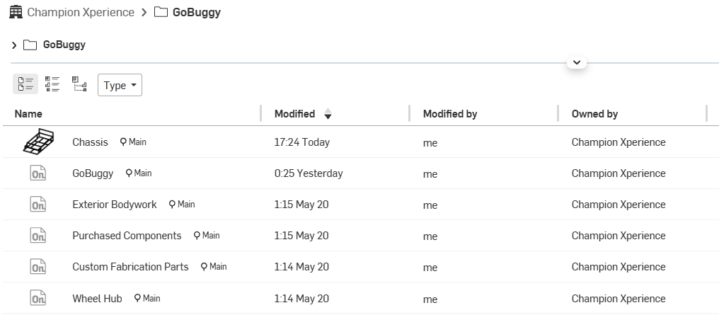
As you can see in the image, we divided our project into six different sections. Thanks to this structure, we prevent any versions or branches from affecting the entire project. We gathered only the data that is interconnected, where a change in one affects the rest, within the same document.
- GoBuggy: The document where the sub and main assemblies will be made.
- Chassis: The document that will contain the chassis, its technical drawings, and cut lists.
- Exterior Bodywork: The document that will contain the design of the car’s outer shell.
- Wheel Hub: The document that will contain the brackets, profile, and assembly forming the wheel hub.
- Custom Fabrication Parts: The document that will contain the designs of brackets, flat bars, threaded rods to be used in the suspension arm system, and profiles to be used in the shock absorber system.
- Purchased Components: The document that will contain off-the-shelf standard components purchased from the market, such as rod ends, rods, 2-way/3-way flanges, corner connectors, shock absorbers, wheels, hub motor, battery, and the seat.
Another advantage of this structure is that you can keep off-the-shelf parts, which you cannot modify but only use in your assembly, directly as Released data through separate documents. With this setup, we have made version, branch, and revision management much more controllable.
Profile Selection for the Chassis
We needed to select the right profile for the chassis. The most important question here was: a welded chassis or a non-welded chassis? The answer to this question was related to the purpose of the product. Our goal in this project was maker-oriented, and we aimed for every maker to be able to easily build it at home. Therefore, we decided to choose a non-welded profile.
However, we still had a lot of options here. Since we wanted to create a project that is open to development, we decided to use a Sigma profile (T-slot extrusion). This way, we would be able to assemble and disassemble everything as we wished, and when we wanted to develop it further in the future, we could easily mount parts thanks to the slots of the Sigma profiles.
Sigma profiles come in many sizes. There are many options like 20×20, 30×30, 45×45, 30×60. Since a load will be carried on it, our preference was 30×30. That also offers options as Light and Heavy within itself. We opted for the 30×30 Heavy Sigma Profile.
How to Create a Custom Profile Library?
We selected the appropriate profile for the car’s chassis. Now, we need to use the exact same profile in the chassis design because, for tests such as load and crash that we will perform, we need to have the exact same geometry and the same material properties of the profile we decided to use in real life. There are many options in the Onshape Frame library. There is a 30×30 Sigma profile option, but the Heavy profile option we prefer is not available. For this reason, we created the sketch of the profile using the dimensions we obtained from the manufacturer.
Onshape allows you to use a sketch located in any document you want as a frame profile.
We could have proceeded this way, but since we wanted the project to be built on a controllable foundation, we decided to create our own custom profile library.
Managing Version Control for Custom Profiles
Pro Tip (1:48-4:19): To create a Profile Library, your document must have a version. The reason for this is entirely to ensure that the data is protected in a controlled manner. A version essentially brings your data to a frozen state. In traditional PDM systems, this state is called Read-Only. Thanks to this, even if any changes are made to the profile sketch in the future, your existing data continues to use the first version. If you want the new version to be used, you need to create a second Version in the document. But do not worry. Even if you create a second version, Onshape does not perform an update automatically. However, it notifies you that there is a new version of it. You can use the new version according to your preference.
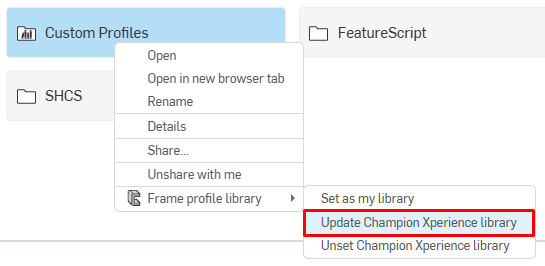
Pro Tip: You can add a new profile geometry into the folder you use as a library. If you want the added profile to appear in your Profile library, you need to perform an update operation via your library folder.
Adding Cut List Properties Using Tags
Pro Tip (0:32/4:19): Using the Tag feature, you can add details inside the profile that you want to appear in the cut list, such as the dimensions of the profile and the name of the company that will produce the profile.
Library Organization Strategy
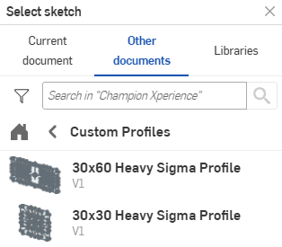
Pro Tip: Your profiles inside the library can be displayed in two ways. The First method is, If you added the sketch belonging to each profile as a separate document into the Library folder, it will appear in the library as Library: Champion Xperience frame profile, Profile: 30×30 Heavy Sigma Profile, and 30×60 Heavy Sigma Profile.
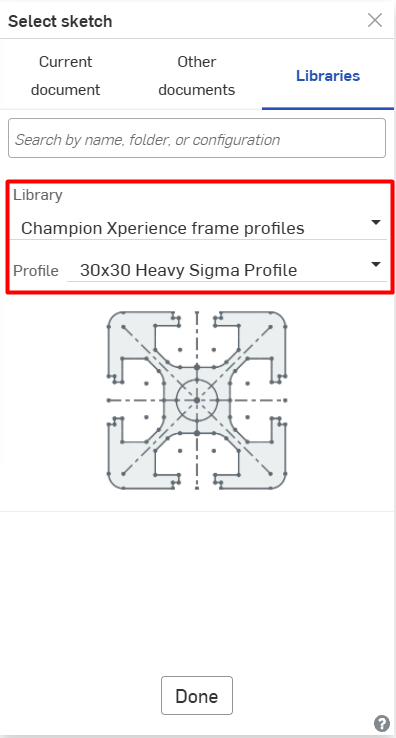
Method 1
The second method is, if you added a single document to the library folder and created different sketch profiles within that document, it would appear in the library as Library: Champion Xperience frame profiles, Type: Heavy Sigma Profile, Profile: 30×30, and 30×60.
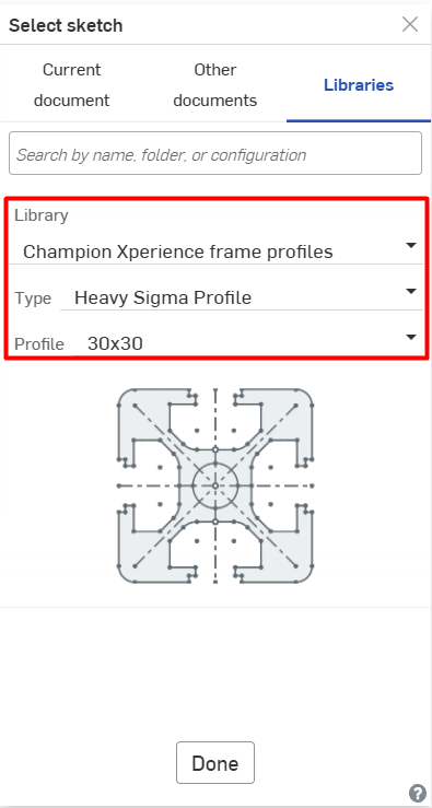
Method 2
So, which one should you choose to create a library? The answer to this question is entirely related to your needs.
The reason we preferred the first method (creating the profiles as separate documents) is if we needed to make a change to the chassis by adding a new profile during any development phase in the later stages of the project, we wanted the other currently used profiles to remain unaffected. Remember, versions created in Onshape are document-centric, not model-centric. In order not to force a version update on all profiles located in the document, we chose this method because we wanted to manage our data independently from each other by creating the profiles as separate documents. If the profile sketches in the profile library you are going to create are interconnected, or if you have a standardized library where you no longer add new profiles, it would make more sense to manage it through a single document.
Using Configurations for Profile Sizes
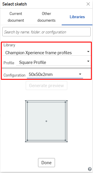
Pro Tip: If you have profiles whose geometry remains the same but dimensions change, Onshape offers a Configuration option here. Since the geometry of the profiles we preferred in our project changed significantly, we did not have the need to use configurations.
How to Design a Chassis
The geometry that will make up the chassis is the most important step of the chassis design. The most important step in frame design is creating the sketch. Once the sketch is created, we can give volume to the chassis with the Sigma profiles we added to the Library. Since we planned the car to be a single-seater, we designed its dimensions so that when a person sits inside, their feet touch the pedals with their knees bent. The chassis sketch basically consists of 3 sections. The front area where the suspension arm system will be, the middle section is the driver’s area, and the rear section is where the hub motor will be attached to the chassis. The volumized chassis consists of the Lower Subframe, Front Bulkhead, Side Rails, and Rear Bulkhead sections. While creating the sketch, we ensured that all the profiles making up the Lower Subframe were positioned relative to the center of mass of the chassis.
Simplifying Sketching with Mate Connectors
Pro Tip (1:22/4:48): If you have complex profiles, the geometries that will form the profiles can take up a lot of your time. You might need to create many planes for interconnected geometries. With the Mate Connector command in Onshape, you can start a new sketch at any location you want without needing planes. Moreover, being able to do this while in the sketch command allows you to save time. The Mate Connector tracks your mouse cursor and snaps to the connection points on your sketch. To easily capture the exact point you want with the Mate Connector, you can hold down the Shift key on your keyboard and make your selection with your mouse. The only thing you need to pay attention to is that the axis system of the Mate Connector where you will draw your sketch must be XY.
Mirroring Symmetrical Sketch Geometries
Pro Tip (1:47-4:48): If your sketch geometries are symmetrical, you can mirror them using the Mirror command just like mirroring a 3D geometry, without needing to redesign them.
Managing Frame Corner Intersections
Pro Tip (2:13-4:48): When working with profiles, determining the Corner type is crucial. Since we will be screwing the Sigma profiles together in the project, we decided to use the Butt corner type. Another point to pay attention to is determining which profile will be on the inside and which will be on the outside. At the corner joints of the chassis, a structure was preferred where the long edge profiles press between the short edge profiles from the inside (remaining on the inner side). To make this adjustment between profile corners, you can use the Corner Overrides feature.
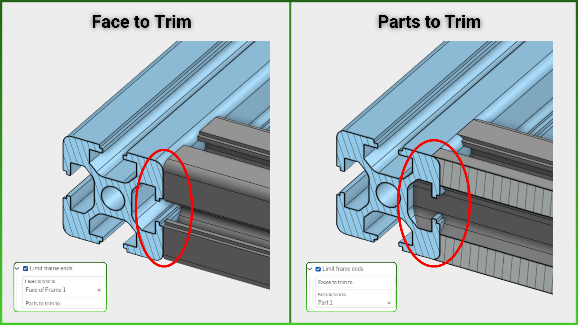
Setting Trimming Limits by Face or Part
Pro Tip (2:35-4:48): You can define limits between touching profiles. It is beneficial to be careful when choosing between the two options: Part and Face. When you select Parts, a trimming operation is applied by taking all contact points between the two profile surfaces as a reference. For example, if you are using a Pipe Profile, this option will make sense. However, if you are using a Sigma profile as in the project, you need to set the limit by Face instead of Parts. The Face limit performs a trim based on the selected face. You can examine the difference between the two from the image below.
Understanding the Trimming Logic
Pro Tip (2:55-4:48): The Faces option for Limit frame ends has some restrictions due to its working logic. For example, if there are profiles touching a profile from both sides, and the limit face is going to be the right and left side faces of the middle profile, the command does not allow this and gives the warning, “Selected planes cannot trim the same frame end. Use Trim feature instead.” In this type of situation, you can perform the trimming operations you want with the Frame trim feature. Furthermore, together with the Ordered groups option within the Frame trim command, you can perform the cutting operation on all your profiles collectively in a single go. Of course, it is worth reminding that the Ordered groups option cuts according to Parts, not Faces, while trimming. Since we were trimming by faces, we performed our operations using the Face option within the command.
How to Create a Cut List
The sine qua non of manufacturing is the cut list. We have completed our chassis design. So, how will we determine the dimensions of the profiles before sending them to production? Of course, we will not do this by measuring each profile one by one. With the Onshape Cut List command, you can quickly generate the dimensions of all profiles in a table format. You can copy this table to an Excel file, send it to the manufacturer, and get a price quote before production.
Linking Profile Tags to Cut Lists
Pro Tip (0:44-3:22): When you create a cut list, if there is a Tag belonging to the profile you added to the library, the information you added inside the Tag comes directly into the cut list table.
Understanding Composite Parts
Pro Tip: When you create a cut list, you can see that a new part named Composite Parts is added to the Parts List area. The Composite Part feature is a command that also works independently. You can have the parts grouped under a single part in your models consisting of multiple parts. This provides you with convenient BOM management in the assembly environment. For profiles, this becomes an automatically running command. When you create a new cut list, it automatically gathers all the parts or the selected parts into Composite parts based on your selection.
Customizing Cut Lists with Column Overrides
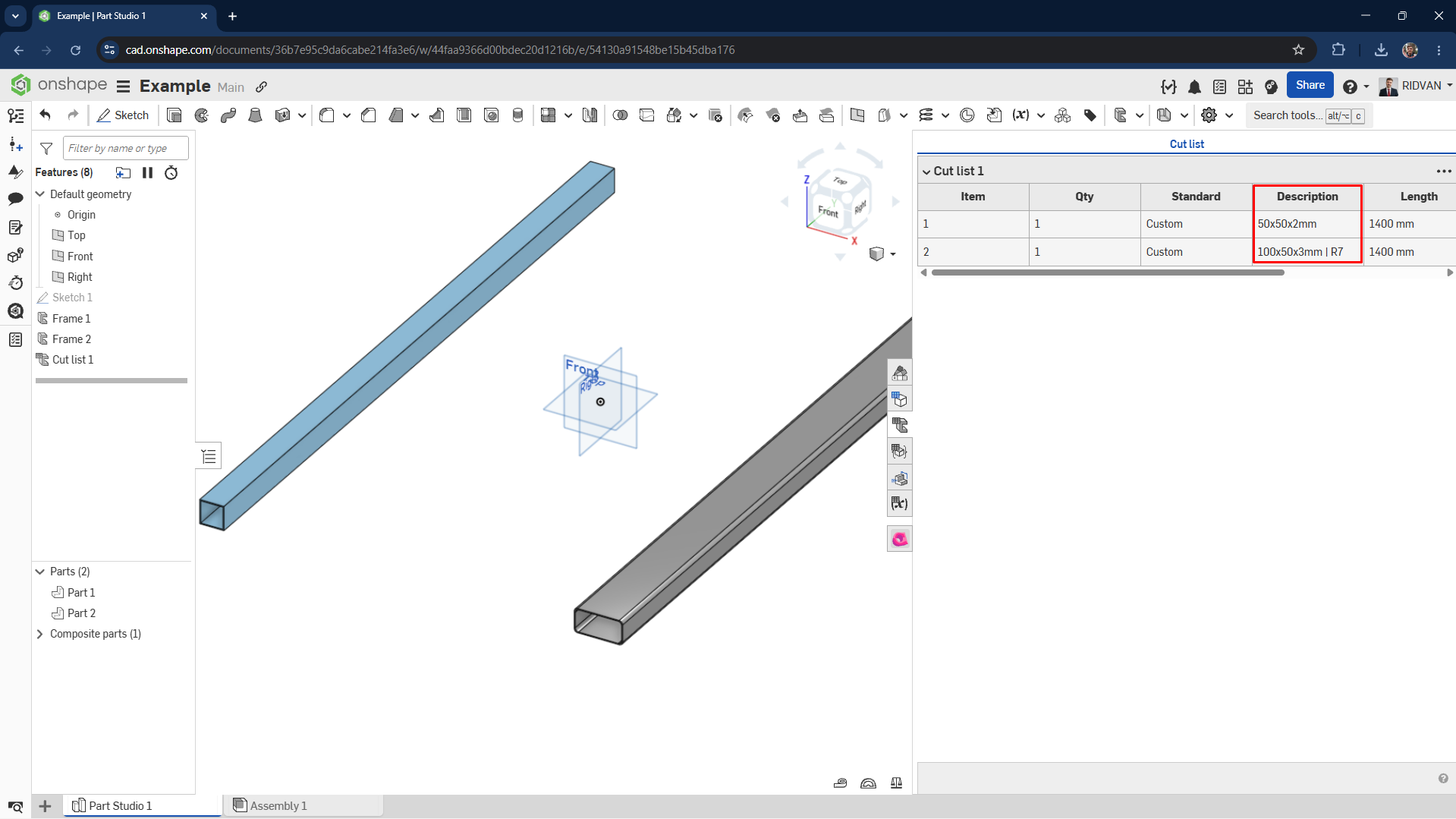
Pro Tip (1:14-3:22): The Cut list command has capabilities beyond offering a standard table option provided by traditional CAD systems. For example, with the Add Column Override option, you can group the profiles under specific columns you desire. In the image below, you can examine a comparative view of a Standard Cut List and a Cut List created with the Add Column Override option.
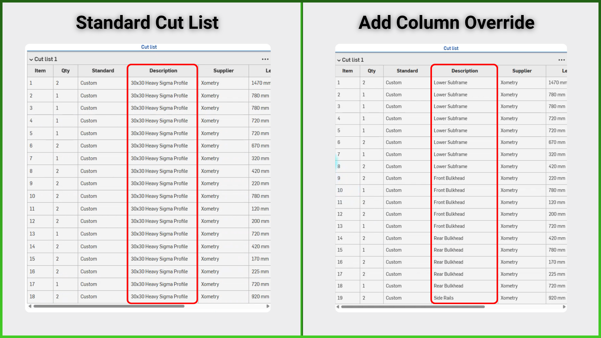
When you examine the image, you can see that I am able to display the regions making up the chassis with new properties on the Cut list by overriding their properties within an existing column (in the project, this column is Description). Instead of overriding the existing column using a standard column name, I can also display the profiles I have divided into groups under that column by giving it a new column name.
Creating Separate Cut Lists for Structural Groups
Pro Tip: Another feature offered by the Cut list is that it allows you to create multiple customized cut lists. For example, instead of seeing all the profiles that make up the chassis on a single cut list, we can also view the structural groups that make up the chassis as separate cut lists. It is beneficial to name the cut lists you created to make them meaningful.
And every time we create a new cut list, we automatically create a Composite Part that gathers the selected profiles under a group. Thanks to this feature, we can show the structural groups belonging to the chassis on separate sheets in the drawing environment. We can ensure that a unique cut list table and callouts linked to the table are created for each structural group. In the upcoming sections of the project, you will be able to learn in detail the impact of Composite Parts on the Drawing and Assembly.
Displaying Configurations in Cut Lists
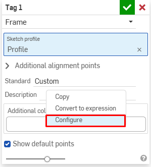
Pro Tip: If your Profile has configurations, you can bring the information belonging to these configurations into the cut list. To do this, you need to make a small adjustment in the Tag command. While in the tag command, you can right-click on the text input box and select the Configure option to specify in which column of the Cut List table you want the Configuration information to appear.
You can see that the Description value is automatically updated according to the configuration selection.
You can also see that this information within the Tag is reflected in the cut list.
Conclusion
In this first part, we detailed our GoBuggy project from initial sketch to chassis design. Next, we will test the chassis under a 200 kg load using Onshape Simulation. Then, we will improve the design based on these results.
Co-Founder at ChampionXperience
Ridvan Polat is a SOLIDWORKS Elite Application Engineer, Founder of ChampionXperience, and a recognized SOLIDWORKS, ENOVIA, and 3DEXPERIENCE Champion. He specializes in CATIA & ENOVIA technical support and 3DEXPERIENCE early engagement adaptation, helping organizations optimize PLM workflows.
Latest posts by Rıdvan Polat (see all)
Subscribe
0 Comments
Oldest

