
© 2023 Created by blog.championxperience.com
Before sending to manufacturing, engineers usually have to make separate 2D drawings to show dimensions and tolerances. This often causes mistakes and slows down work.
With Onshape MBD, all product information is added directly inside the 3D model in the cloud, keeping design, manufacturing, and inspection teams in sync and making collaboration faster and easier.
Now, let’s explore how MBD works and why it matters for your workflow.

What is Model-Based Definition (MBD)?
Onshape MBD is a way to define a product directly inside the 3D model. Rather than using separate 2D drawings to show dimensions, tolerances, and notes, all this information can be found inside the Part Studio alongside the geometry.
This information is called Product Manufacturing Information (PMI). It includes dimensions, tolerances, datums, and annotations needed for manufacturing and inspection.
With this approach, the 3D model becomes more than just a shape. It becomes a complete product definition. It clearly shows how the part should be made, measured, and verified.
This helps reduce confusion and makes communication easier between design, manufacturing, and inspection teams.
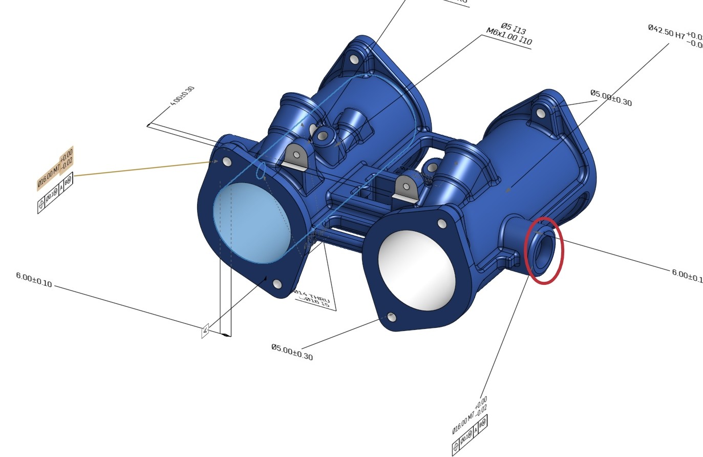
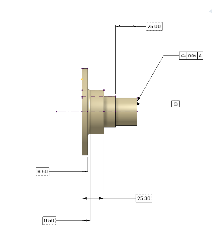 Fig. 1: Flange Front View with Model-Based Definition (MBD)
Understanding Onshape MBD
In Onshape MBD, we work directly on the model to define:
- Dimensions and tolerances
- Datums and GD&T
- Weld symbols and annotations
- Inspection characteristics
All this data is connected to the geometry. When the model changes, the PMI updates automatically.
This means we do not need to update drawings manually or worry about outdated information. Everyone always works with the latest version of the design.
Key Advantages of Onshape MBD
- Always Updated with Design Changes
When we modify the geometry, all related dimensions and tolerances update automatically.
This helps avoid errors caused by old or incorrect drawings. It also saves time because we do not need to update documentation manually.
- Less Dependence on 2D Drawings
MBD does not fully replace drawings, but it reduces the need to create and maintain them.
Instead of repeating the same information in multiple places, we define everything once in the model. This makes the workflow faster and cleaner.
- Ready for Inspection
Inspection teams can use the model directly. They do not need to recreate dimensions or tolerances from drawings.
Onshape MBD works with many third-party CMM systems. This helps teams measure parts faster and with fewer mistakes.
- Easy Tolerance Management
We can define default tolerances based on company standards.
If a dimension does not have a specific tolerance, the system applies the default automatically.
This ensures consistency and saves time, especially in large projects.
- One Source of Truth
All product information is stored in one place: the 3D model.
This avoids problems like:
- Missing information
- Different versions of files
- Confusion between teams
Everyone works on the same data, which improves collaboration.
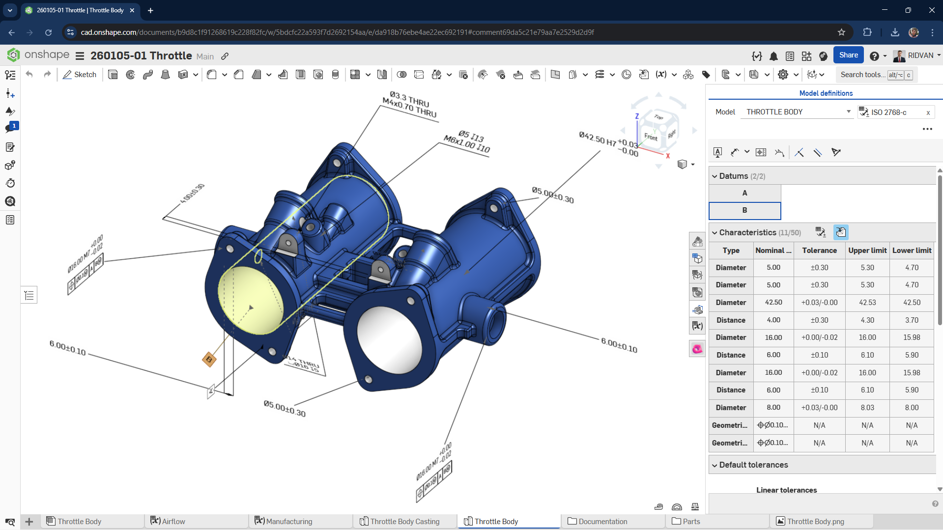
MBD Fundamentals: Inspection Table Interface
The Inspection Table is a key part of the Onshape MBD workflow. It shows all PMI in a clear and organized way.
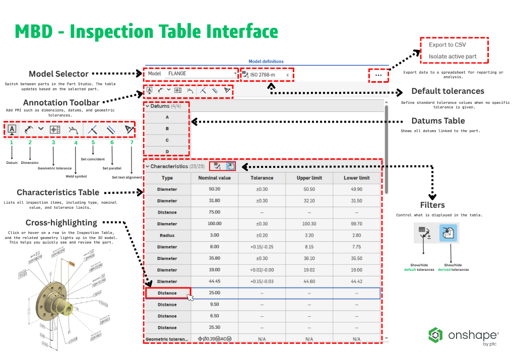
Fig. 2: Flange MBD Inspection Table Interface
Main elements include:
- Model Selector: Switch between parts in the Part Studio. The table updates based on the selected part.
- Default Tolerances: Define standard tolerance values when no specific tolerance is given. (Learn how to create default tolerances.)
- Export to CSV: Export data to a spreadsheet for reporting or analysis.
- Isolate Active Part: Focus on one part by making others transparent.
- Annotation Toolbar: Add PMI such as dimensions, datums, and geometric tolerances.
- Datums Table: Shows all datums linked to the part.
- Characteristics Table: Lists all inspection items, including type, nominal value, and tolerance limits.
- Filters: Control what is displayed in the table.
One important feature is cross-highlighting.
When we hover over or click on a row in the table, the related geometry is highlighted in the graphics area. This makes it easier to understand and review the model.
 Fig. 3: Interactive cross-highlighting between GD&T table and 3D model
Creating Model Definitions
When we add PMI in Onshape:
- The Inspection Table updates automatically
- Annotations stay linked to geometry
- We can adjust annotation positions using constraints
- Each configuration can have its own tolerances
Also, sketch dimensions can be used as inspection characteristics once they are fully defined.
This makes the workflow smooth and keeps everything connected.
 Fig. 4: Activating MBD from Sketch to Feature Creation in the Flange Model
Reviewing and Editing MBD Data
Onshape makes it easy to review and update MBD data.
We can:
- Show or hide annotations from derived geometry
- Use cross-highlighting to check relationships
- Delete annotations and automatically update the table
This helps keep the model clean and accurate.
Fig. 5: Editing MBD data in Onshape with automatic Inspection Table updates
Model Validation
Sometimes changes in the model can create issues between geometry and PMI.
Onshape detects these problems and shows that the model needs review.
To keep the model valid:
- Characteristics must reference correct geometry
- Errors must be reviewed and fixed
- We can compare versions to track changes
This ensures the model is ready for manufacturing and inspection.
Downstream Integration and Data Exchange
Onshape MBD supports export to STEP AP242 format.
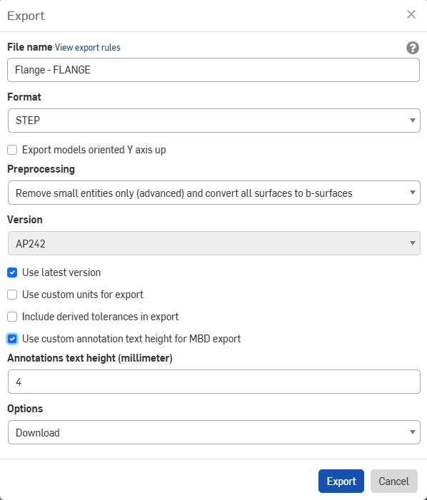 Fig. 6: STEP AP242 Export Dialog with PMI Enabled
This format includes both geometry and PMI. It allows other systems to read:
- Dimensions
- Tolerances
- Annotations
This is useful for:
- Inspection software
- CMM programming
- Other CAD systems
It helps avoid manual work and improves accuracy.
Below is an example of a file exported from Onshape and successfully imported into Creo with all defined 3D PMI fully preserved.
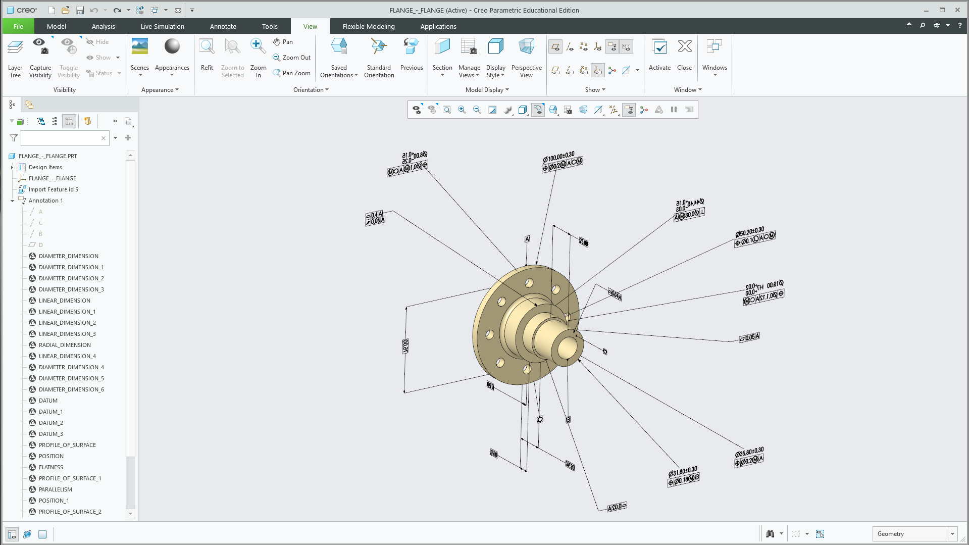 Fig. 7: Onshape model imported into Creo with all PMI preserved (Both Onshape and Creo are PTC products).
What Makes Onshape MBD Different?
Onshape offers a different approach compared to traditional CAD systems.
In many tools, MBD is a separate feature or add-on. In Onshape, it is built directly into the modeling environment.
Because Onshape is cloud-native:
- We can access everything in the browser
- We do not need to export files to share data
- Version control is automatic
- Teams can work together in real time
This makes collaboration easier and faster.
Onshape MBD: All-in-One Platform for GD&T and Manufacturing Collaboration
Onshape MBD brings GD&T, communication, and manufacturing workflows together in a single cloud-native environment. Engineers can define product requirements, collaborate with team members, and make decisions directly within the 3D model—without relying on separate drawings or disconnected tools.
 Fig. 8: Geometric tolerance types in Onshape MBD
The following video shows how engineers apply GD&T, communicate through comments, and collaborate in real time—all within the same 3D model.
Real Collaboration Scenario
To better understand how Onshape MBD improves communication, let’s look at a real collaboration scenario between a design engineer and a production engineer.
In this example, the team is defining datums for a flange part to ensure proper machining and alignment during production.
Scenario
Design Engineer (Hanen Bdioui Polat)
Hello @RIDVAN, I set Datum A (flange surface) for the shaft bores. For machine zero (Datum B), the outer surfaces marked in red are too rough. Is the tagged main bore the ideal reference for fixturing? Can you confirm and add Datum B?
Production Engineer (Ridvan Polat)
Hello @HANEN BDIOUI, you’re absolutely right. The main bore (Ø42.50) is the most stable surface for centering. I tagged Datum B to the dimension and I’m setting up the CNC routing accordingly.
Design Engineer (Hanen Bdioui Polat)
Great, thanks for the collaboration. MBD is complete, we can proceed to production.
What This Demonstrates
This example shows how Onshape MBD connects design and manufacturing teams through a shared 3D model.
The video starts with a desktop (PC) workflow, then continues on a tablet, and finally on a mobile device—demonstrating how engineers can seamlessly access and interact with the same model across different platforms.
Instead of relying on separate drawings and external communication, all interactions—GD&T definition, comments, and decision-making—happen directly within the model. Engineers can clearly reference geometry, assign tasks, and respond in real time.
Why It Matters
- Work from Anywhere: Access the same model on PC, tablet, or mobile device
- Faster Communication: Questions and decisions are handled instantly within the model
- Better Clarity: Tagged geometry and markup eliminate ambiguity
- Real-time Collaboration: Design and production stay aligned at every step
- Single Source of Truth: All information is centralized and always up to date
Onshape MBD is not just a way to define dimensions and tolerances—it’s a platform that enables teams to collaborate anytime, anywhere, reduce errors, and move from design to production with confidence.
What are the main differences between MBD and traditional 2D drawings?
| Aspect | MBD | Traditional 2D |
| Data Source | The 3D model contains all the PMI and becomes the main reference. | Information is split between drawings and other documents. |
|---|---|---|
| Clarity | Working directly in 3D makes it easier to read and understand the design. | 2D views can be difficult to interpret, especially for complex parts. |
| Collaboration | Teams work from the same model, so everyone stays aligned. | Risks ending up with different or outdated versions of drawings. |
| Changes | When we update the model, the changes are reflected everywhere. | Updates have to be done manually on each drawing. |
| Manufacturing | The model can be used directly for manufacturing processes like CAM. | Data needs to be reinterpreted before it can be used in production. |
| Efficiency | Helps reduce errors and saves time during the design process. | Takes more time and increases the risk of mistakes. |
Impact on Manufacturing and Inspection
With Onshape MBD, manufacturing teams can work directly from the 3D model.
They do not need to wait for drawings. All required information is already inside the model.
Inspection teams can also use the model to create measurement programs. This reduces manual work and improves accuracy.
Overall, this leads to:
- Faster production
- Fewer errors
- Better communication
Do We Still Need 2D Drawings?
In some cases, yes.
Some customers or industries still require drawings for documentation or approval.
However, in many workflows, the 3D model with PMI is enough. It can fully define the product without additional documents.
Everything in One Place: The 3D Model
Onshape MBD changes how we define and share product information. Instead of separating geometry and documentation, we bring everything into one place: the 3D model.
This makes the workflow: Simpler, faster, and more reliable
By using MBD, we improve communication, reduce errors, and support better collaboration between teams.
For engineers and companies looking to modernize their workflow, Onshape MBD is a strong and practical solution.
Sales Development Representative at ChampionXperience
Hanen Bdioui is the Editor-in-Chief at ChampionXperience, where she leads content on CAD, VR, and emerging engineering technologies. She works with Dassault Systèmes as a Content Creator and SOLIDWORKS Application Engineer, and contributes as a technical writer for Engineering.com and EngineeRules, covering topics in CAD, PLM, and simulation. Hanen also creates specialized content for 3DEXCITE, the 3DEXPERIENCE platform, and Onshape, supporting engineers and companies in adopting modern digital workflows.
Latest posts by Hanen Bdioui (see all)
- How to Create a Custom Material in SOLIDWORKS - 15 May 2026
- Onshape MBD: All in One Place for Design, GD&T and Manufacturing - 18 April 2026
- MySession Missing in SOLIDWORKS Design? Fix It in Less Than 1 Minute - 6 March 2026
Subscribe
0 Comments
Oldest
