
© 2023 Created by blog.championxperience.com
The coil spring of the shock absorber on my RC car, which I previously designed using SolidWorks and xDesign and produced with a 3D printer, has reached the end of its life. The coil spring, which I printed using PETG filament, lost its elasticity. Actually, it had a soft spring rate. While revising the RC car, I decided to improve this part as well. My goal was to increase the stroke travel of the spring, and to obtain a spring with a higher spring rate. This improvement process actually turned into a complete Design for Additive Manufacturing (DfAM) application. In this blog post, we will examine everything in detail, from how an appropriate coil spring design for 3D printing should be, to what the spring rate depends on, and the filaments that should be used for printing.
How to Design a Coil Spring?
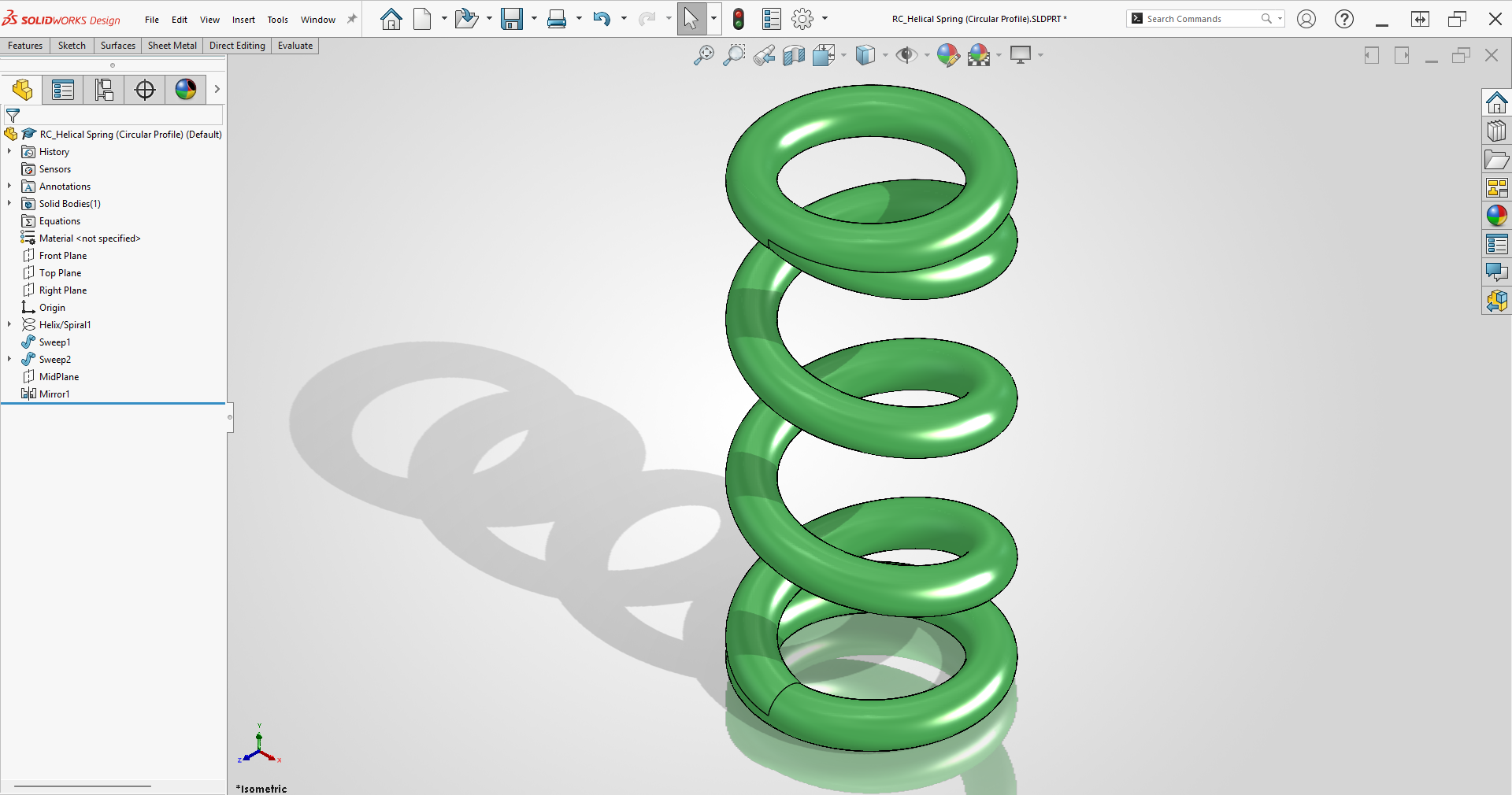
I can say that spring design is done in almost the same way in many CAD programs I have experienced. You need two things for spring design: a circle sketch that will determine the diameter of the spring, and the helix/spiral command that will give the spring its helical shape.
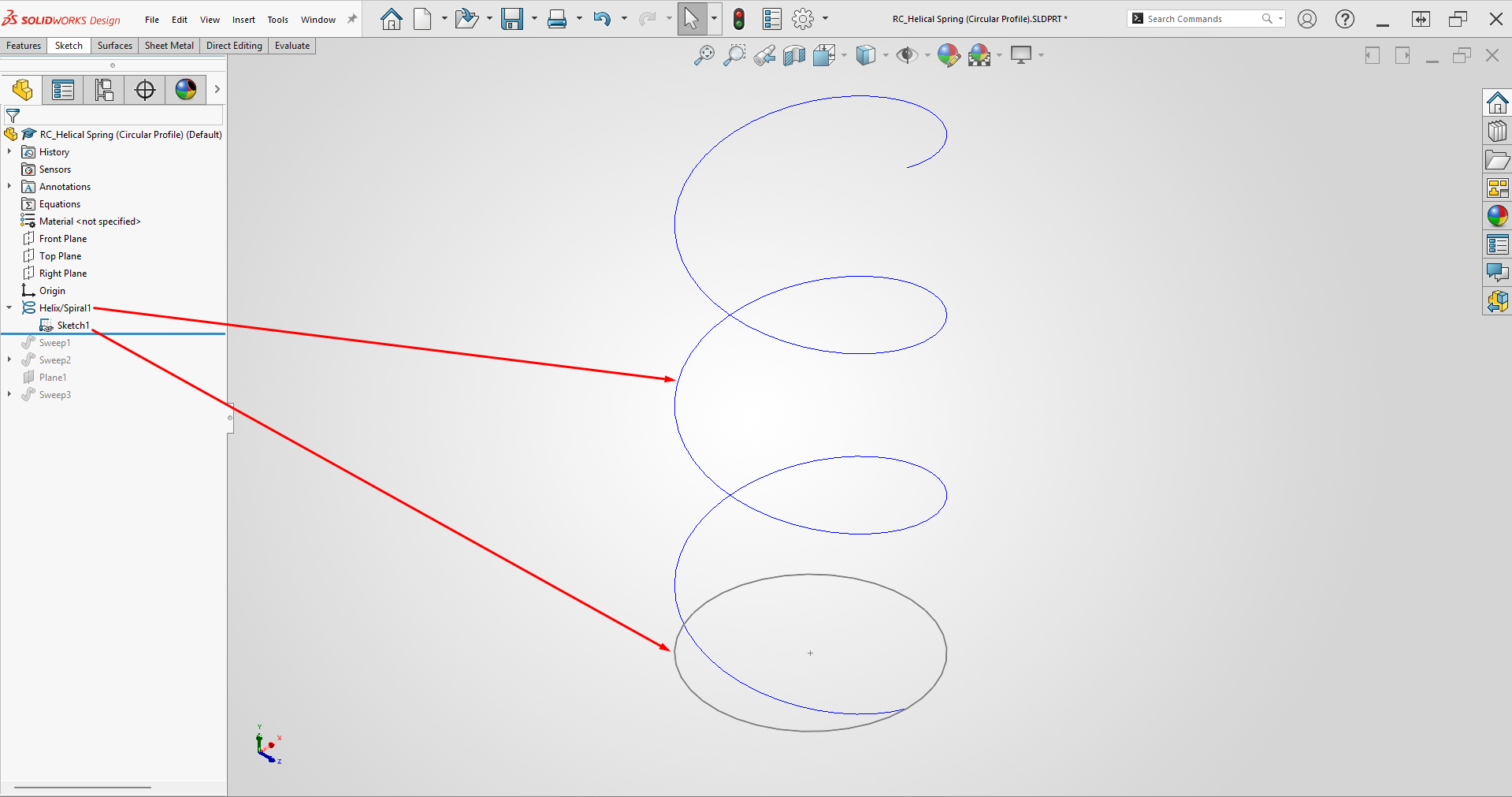
The next steps may differ depending on the design program you are using. We will proceed according to SOLIDWORKS commands here. We need a spring profile to create the solid shape of the spring. Afterward, you can create the 3D shape of the spring by selecting the profile and the path (the path is the helix here) with the Sweep command. However, coil spring profiles are generally circular, and the circular profile option is readily available within the SOLIDWORKS Sweep command. Therefore, you do not need to create any profile.
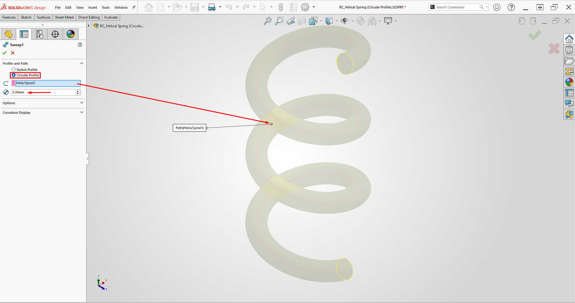
As shown in the image above, when you select the Circular Profile option, the profile is automatically set as a circle. All that is left is to determine the diameter of this circle, and select the helix as the path.
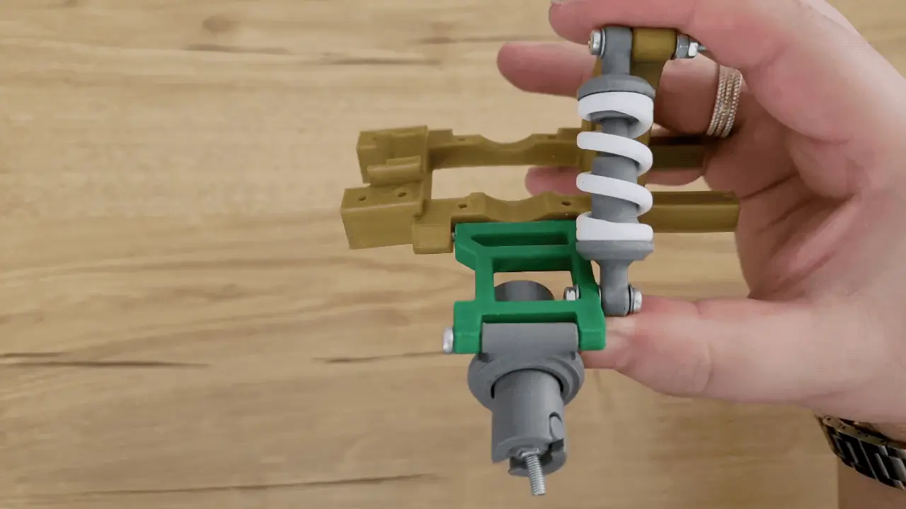
Since I will use this spring in a shock absorber system, I am making the top and bottom contact surfaces circular. For this, you can use the Sweep command along with the circle sketch we previously created for the spring diameter in the Helix command.
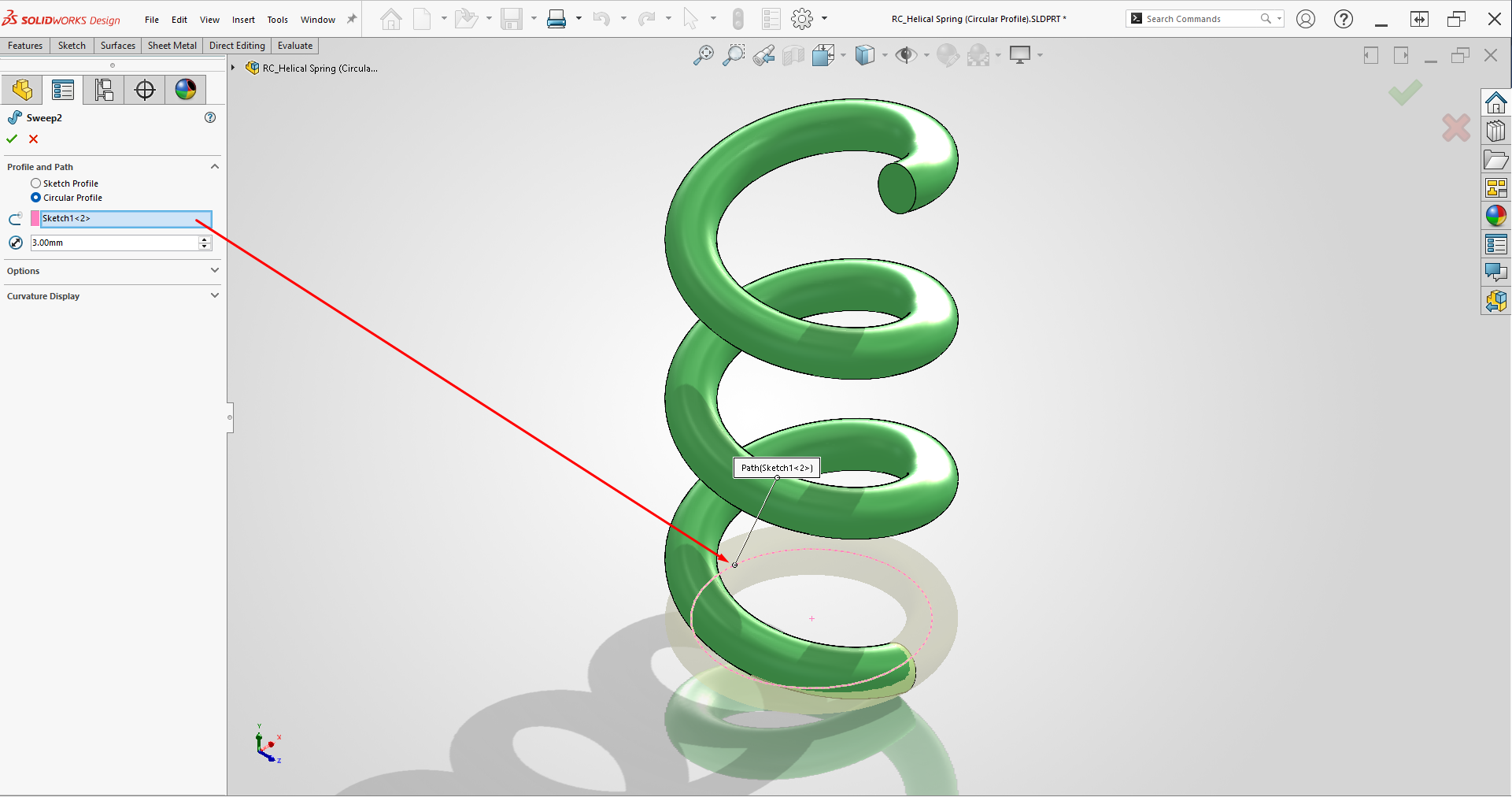
This torus-shaped part we created at the bottom will ensure it sits properly in its slot on the shock absorber. We create the final shape of the spring by creating a plane in the middle of the model, and mirroring the torus to the top.
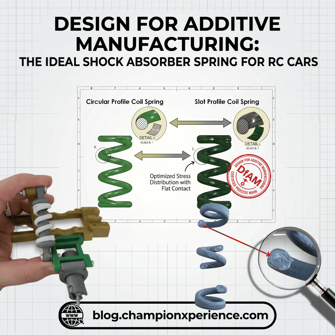
Slot Profile Coil Spring Design
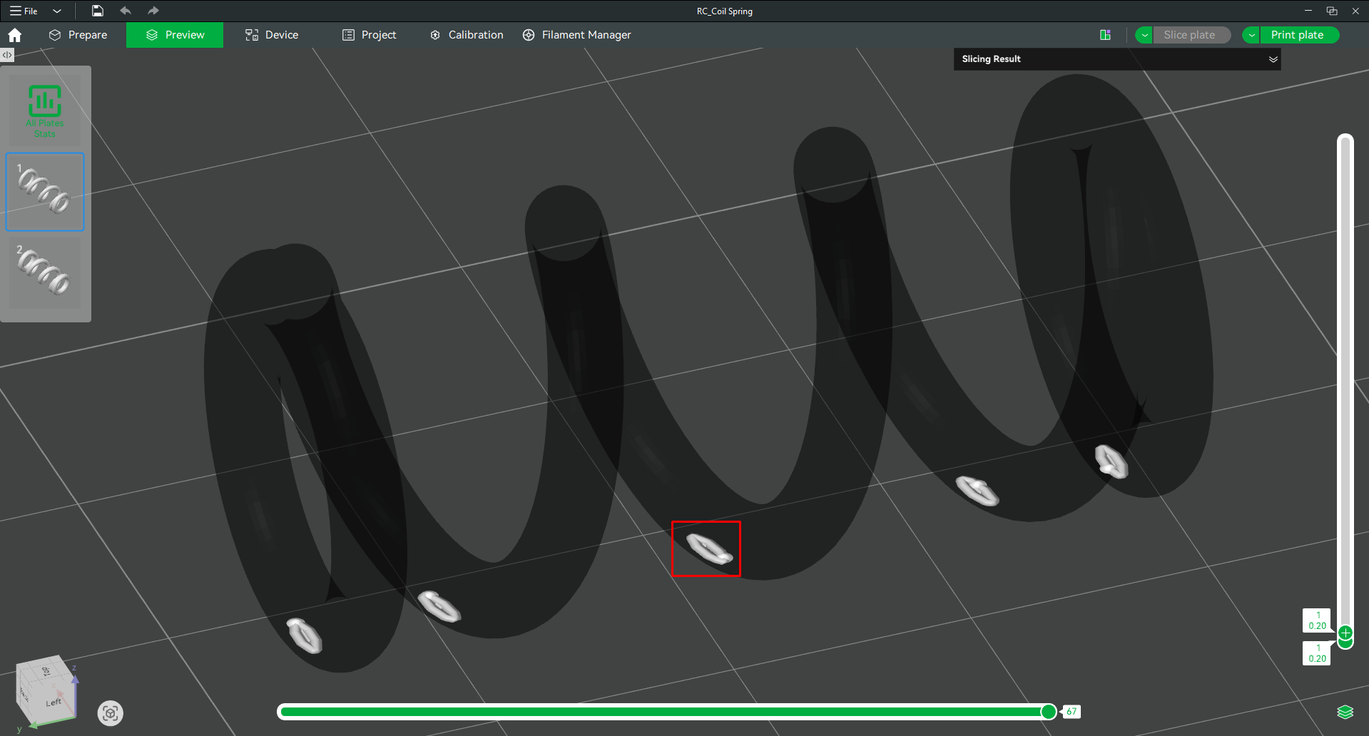
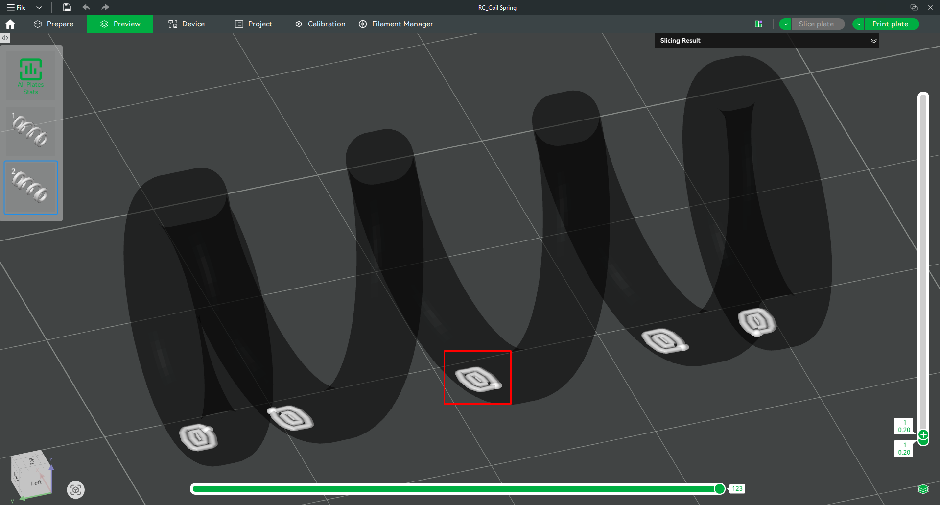
Traditional springs have a circular profile, as I showed in the example. When you want to produce a spring using FDM technology, you will see that circular profile springs do not perform very well. Especially minimal springs used for an RC car become excessively fragile. Another problem is that their contact area with the printer bed is very small, making printing difficult. As I showed in the slicer software, the first layer contact of a circular profile spring is very minimal, which makes printing difficult. Here, of course, we can solve the problem by adding a brim and supports to provide better bed adhesion.
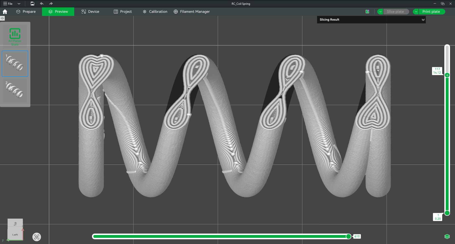
If we examine the cross-section at the layer height where the spring coils merge as a whole during the rest of the print, we can see again that the bonding is happening over a very small area.
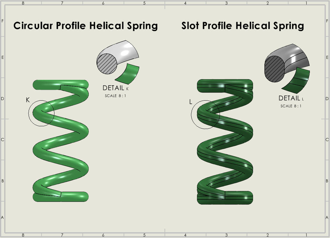
As a result of my tests, I observed both that bed adhesion is difficult and that the spring breaks after a few compression cycles. To overcome this problem, I decided to change the design of the spring profile. When I used a slot spring profile instead of a circular profile, I achieved better bed adhesion and a stronger spring thanks to the flat surfaces. I showed the differences between the spring profiles in the image below.
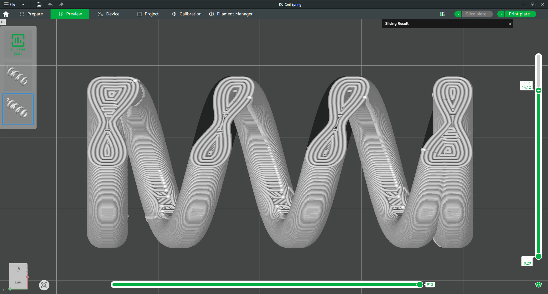
When we examine it through the slicer software, you can see that the tiny flat surfaces cover a larger area in the first layer compared to the circular profile spring.
If we examine the cross-section at the layer height where the spring coils merge as a whole during the rest of the print, you can observe that the bonding is done over a much wider surface compared to the circular profile.
After observing the varying durability based on the spring profiles, I asked myself the following question: Why do circular profile springs break faster, while slot profile springs lasted for years and did not break?
The Impact of FDM Technology and Anisotropy
The main reason underlying this issue lies in the 3D printing technology used. I use a 3D printer with FDM technology. Parts produced with FDM technology have an anisotropic structure. So, what does anisotropic mean? An anisotropic structure behaves in the exact opposite way of an isotropic structure. While a material with an isotropic structure exhibits the same mechanical properties in every direction (injection molding is an example), a material with an anisotropic structure does not exhibit the same mechanical behavior in every direction. In its simplest form, the strength in the XY plane and the interlayer strength in the Z axis are different from each other.
In Circular Profile Springs: The contact point of two overlapping circular layers is tangential. Due to geometry, the layers only adhere to each other in a very narrow area. This situation creates a very weak bond in the Z axis, and layer separation (delamination) easily begins from these narrow contact surfaces while the spring is working.
In Slot Profile Springs: Thanks to the flat parts of the profile, the contact surface of the overlapping layers is much wider. The polymer chains bonding over a wide surface area create a much more resistant structure against the shear and torsional forces that occur when you flex the spring.
I stated the two most obvious reasons above. Apart from these, we can list many factors such as toolpaths created by the slicer software, overhangs, and the notch effect.
So, is the slot profile alone a sufficient design? Actually no. As long as the correct filament is not selected, it becomes as fragile as a circular profile spring. Now, let’s examine the effect of material selection on durability together.
Choosing the Right Material for the Coil Spring
I used 3 different materials while conducting the tests: PLA, PETG, and ABS. I used my slot profile spring design while performing these tests.
PLA Test: The spring could not maintain its spring behavior for long, and after a certain amount of use (in a short time), it first cracked and then broke completely.
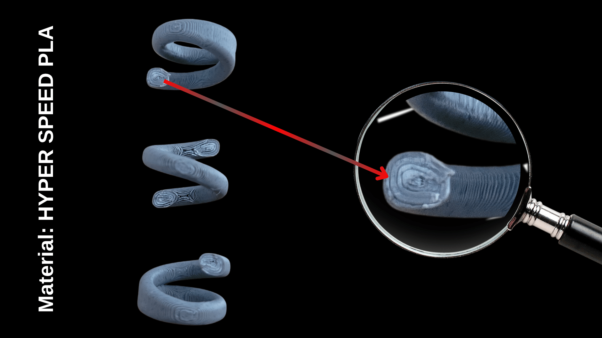
In the image, I showed the fracture surface closely under a lens. The fracture surface is completely flat, just like it was cut with a knife. You can see that there is no sign of stress whitening, elongation, or necking at the edges to indicate that the material yielded before breaking. This indicates that PLA cannot tolerate flexing and, upon reaching its limit, suddenly cracks and breaks like glass.
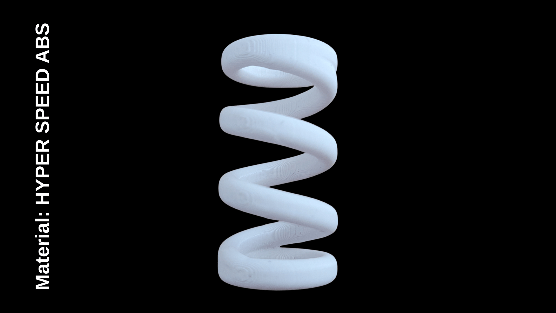
ABS Test: The spring still continues to maintain its spring behavior. In the event of any breakage, I will update the image and share the necessary comments with you.
But why did PLA fail while ABS endured? PLA is inherently a brittle material. ABS, on the other hand, is a ductile material.
PLA vs. ABS by Material Structure
- PLA does not tolerate flexing well.
- Its yield strength is higher than that of ABS.
- When flexing motions are applied, micro-cracks form between the polymer chains, and these cracks propagate rapidly, turning into a structure that suddenly cracks and breaks like glass.
- It has an elongation at break ranging from 6% to 10%.
- The polybutadiene component in ABS gives it the ability to flex and absorb impact.
- Its flexing ability is so strong that even if it is flexed repeatedly, it is highly resistant to forming micro-cracks. It absorbs the energy and returns to its original shape.
- It has an elongation at break ranging from 20% to 40%.
PLA vs. ABS by Printing Conditions
- PLA offers easy printing on many printers, including open-system printers.
- The part cooling fan runs at 100%. In new generation high-speed printers, the auxiliary side fan also provides massive cooling. The moment the nozzle deposits the molten plastic onto the previous layer, the plastic cools and solidifies rapidly within seconds. In this case, the top layer adheres to the bottom layer only superficially. They do not entangle at the molecular level.
- ABS requires enclosed printers and keeping the ambient temperature at a certain level within the chamber. (You might be printing ABS on open-frame printers, but it is worth noting that this does not mean you are fully utilizing the properties of ABS.)
- While printing ABS, the chamber temperature is kept in the range of 45-60 degrees Celsius, and the side fan is turned off. The part cooling fan is either off or operates at a low rate. When the nozzle lays down a new layer, since the layer below is still hot (close to its glass transition temperature), it slightly remelts with the heat of the newly arriving hot plastic. In this case, the polymer chains of the top layer and the bottom layer penetrate each other and entangle.
In summary, while PLA is a great choice for prototypes that will sit on a display shelf or remain under static loads, ABS will be a better choice when dynamic loads involving mechanical behaviors come into play.
PETG Performance (The Middle Ground)
I did not run a new test for PETG. Because when I first built my RC car project years ago, I used PETG instead of PLA. Although it worked properly for a long time, it lost its elasticity after a certain period.
PETG is positioned between PLA and ABS. It exhibits a more ductile material property compared to PLA, while being more brittle compared to ABS. It is easier to print than ABS.
So, I ask this question: What determines whether a spring is soft or stiff? Is it only the material selection? The answer is no. Material selection is one of the factors. In that case, let’s take a look at how the Spring Rate value, which indicates the stiffness or softness of the spring, is calculated.
How to Calculate the Spring Rate?
Many variables determine the stiffness or softness of a spring. Variables such as the wire diameter (d), mean coil diameter (D), number of active coils (n), and the material’s shear modulus (G) determine the spring rate. You can calculate the spring rate using the following formula:
$$k = \frac{G \cdot d^4}{8 \cdot n \cdot D^3}$$
So, what is this spring rate?
Spring rate (k) indicates the force required to compress the spring by 1 mm. The lower the k value, the softer the spring, and the higher the k value, the stiffer the spring.
Handling Characteristics: Soft vs. Stiff Springs
To understand the difference between a soft spring and a stiff spring, we need to examine their characteristic effects:
- Soft Springs: Maximize traction and make responses more predictable, but steering precision slows down (gives a sluggish feel).
- Stiff Springs (Hard Springs): Sharpen steering response (snappy response) and increase chassis stability, but they can cause the chassis to bounce on bumpy surfaces, completely eliminating traction.
The Golden Rule: The generally accepted engineering approach in motorsports and RC track tuning is this: “Use the softest spring possible that is stiff enough to prevent the vehicle from bottoming out and rolling over under high grip.” An overly stiffened suspension system always means sacrificing mechanical grip.
This calculation is valid for a standard spring, meaning springs with a circular profile. The calculation for slot profile springs is done using the following formula:
$$k = \frac{4 \cdot G \cdot J}{\pi \cdot n \cdot D^3}$$
$$J \cong \frac{A^4}{40 \cdot I_p}$$
I will not go into the calculation details here. If any of you are curious, I can update my blog post by adding the details. Right now, our focus is to show how to create the most accurate spring design for 3D printing. Therefore, I will just provide the results of the calculations.
To perform the calculation, we also need the Shear Modulus (G) values of the materials. According to my research on the internet, I found the following values for the average G value:
- PLA: 1100 MPa
- PETG: 800 MPa
- ABS: 750 MPa
Circular Profile Spring Rate
Design Specifications:
- Option 1: Number of Coils 4, Length 31 mm, Mean Coil Diameter 14 mm, Wire Diameter 3 mm
- Option 2: Number of Coils 3, Length 38 mm, Mean Coil Diameter 14 mm, Wire Diameter 3 mm
- Formula Used:
$$k = \frac{G \cdot d^4}{8 \cdot n \cdot D^3}$$
| Material | Option 1 (k) | Option 2 (k) | Stiffness Increase Rate |
| PLA | 1.01 N/mm | 1.35 N/mm | %33.6 |
| PETG | 0.74 N/mm | 0.98 N/mm | %32.4 |
| ABS | 0.69 N/mm | 0.92 N/mm | %33.3 |
When the results are examined, you can see that as the number of coils decreases, the stiffness of the spring increases by an average of 33%. You can also see that a 4-coil spring printed with PLA is stiffer than a spring printed with ABS. Even if the goal is to reach a soft spring rate by increasing the number of coils, the effect of the material is still much more dominant.
Slot Profile Spring Rate
Design Specifications:
- Old Design: Number of Coils 4, Length 31 mm, Mean Coil Diameter 14 mm
- New Design: Number of Coils 3, Length 38 mm, Mean Coil Diameter 14 mm
- Formula Used:
$$k = \frac{4 \cdot G \cdot J}{\pi \cdot n \cdot D^3}$$
Since this is not a circular spring profile, the cross-sectional area of the spring profile must be calculated. The slot profile consists of two semi-circular areas and one rectangular area. When the necessary calculations are made, the Area (A) is found to be 10.68 mm².
| Material | Old Design (k) | New Design (k) | Stiffness Increase Rate |
| PLA | 1.96 N/mm | 2.62 N/mm | %33.6 |
| PETG | 1.43 N/mm | 1.90 N/mm | %32.4 |
| ABS | 1.34 N/mm | 1.78 N/mm | %33.3 |
If we compare the results for ABS with the circular profile springs, the 4-coil spring increased from 0.69 N/mm to 1.34 N/mm. The wide cross-sectional area created by the slot profile provided a 94% increase in the spring rate. Of course, this caused the spring to be much stiffer.
Previously, I was using a 4-coil spring with PETG filament, and I calculated the k value as 1.43 N/mm. In my new design, I reduced the number of coils to 3 and chose ABS as the material. The k value became 1.78 N/mm. The spring rate between the old design and the new one increased by 24.5%.
Optimizing Coil Spring Travel and Fatigue Life
The new design achieves a better operating travel by decreasing the number of coils and increasing the overall spring length. The old configuration featured 4 active and 2 passive coils, with a total spring length of 31 mm. By comparison, the new iteration reduces the active coils to 3 while keeping the passive coils at 2, expanding the total spring length to 38 mm. For both configurations, the profile thickness of the slot remains 4 mm.
Old Design: Spring Travel Calculation
$$L_s = 6 \text{ coils} \times 4 \text{ mm} = 24 \text{ mm} \quad \text{(Solid length of the spring)}$$
$$S_{max} = 31 \text{ mm} – 24 \text{ mm} = 7 \text{ mm} \quad \text{(Maximum theoretical travel)}$$
$$S_a = 4 \text{ active coils} \times 0.1 \times 4 \text{ mm} = 1.6 \text{ mm} \quad \text{(Minimum safety clearance)}$$
$$S_{net} = 7 \text{ mm} – 1.6 \text{ mm} = 5.4 \text{ mm} \quad \text{(Safe travel the spring can operate within)}$$
New Design: Spring Travel Calculation
$$L_s = 5 \text{ coils} \times 4 \text{ mm} = 20 \text{ mm} \quad \text{(Solid length of the spring)}$$
$$S_{max} = 38 \text{ mm} – 20 \text{ mm} = 18 \text{ mm} \quad \text{(Maximum theoretical travel)}$$
$$S_a = 3 \text{ active coils} \times 0.1 \times 4 \text{ mm} = 1.2 \text{ mm} \quad \text{(Minimum safety clearance)}$$
$$S_{net} = 18 \text{ mm} – 1.2 \text{ mm} = 16.8 \text{ mm} \quad \text{(Safe travel the spring can operate within)}$$
With these calculated specifications, necessary design changes were also implemented in the shock absorber design to prevent the coils from touching each other during compression. So, what was the benefit of this change?
When the old and new designs compress by the same amount, for example, 4 mm, the stroke utilization rate of the total capacity is 74% in the old spring, while it is 23% in the new spring. This offers a comfortable operating range and means a significant improvement in the fatigue life of the spring. While the stress on the polymer chains is felt at high levels in the old spring, it is felt much lower in the new spring design. This allows it to work for a longer period. In the old spring, the probability of coil bind during sudden impacts, meaning the spring is fully compressed and the coils crash into each other to suddenly lock up, is higher. The new spring has the necessary stroke clearance to absorb sudden impacts. Since the stroke clearance is less in the old spring, it works harshly, and the impacts on the shock absorber are felt on the chassis. Since there is a wider stroke clearance in the new spring, a smoother and more predictable response will emerge.
Conclusion — Access the Model
In this blog post, I shared my experiences regarding how a spring design for 3D printing should be. If you have an RC car and want to print and use springs with your 3D printer, this blog can be a guide for you. If you do not have design experience and are looking for a print-ready 3D model for your RC car, you can use my design via the link below. Moreover, you can buy it at a very affordable price for a limited time.
Click the link to take advantage of the discount: Shock Absorber for RC Car
Co-Founder at ChampionXperience
Ridvan Polat is a SOLIDWORKS Elite Application Engineer, Founder of ChampionXperience, and a recognized SOLIDWORKS, ENOVIA, and 3DEXPERIENCE Champion. He specializes in CATIA & ENOVIA technical support and 3DEXPERIENCE early engagement adaptation, helping organizations optimize PLM workflows.
Latest posts by Rıdvan Polat (see all)
Subscribe
0 Comments
Oldest
