
© 2023 Created by blog.championxperience.com
SOLIDWORKS top-down design is the answer to a problem many mechanical engineers know all too well. Have you ever experienced that sinking feeling when a mechanical assembly you spent days refining is completely ruined by a “minor” dimensional change?

In traditional “Bottom Up” design, this kind of revision often leads to exploded mates, broken references, and hours of manual rework. But what if your design wasn’t a static stack of parts, but an “intelligent” system that adapts instantly to change?
In this article, we will explore the power of the Top-Down Design method in SOLIDWORKS. Using a complex Slat mechanism as a case study, I will demonstrate how to drive all components from a single Master Layout Sketch, thereby eliminating revision anxiety and maintaining full control over design changes.

Step 1: A Shift in Mindset – Designing Directly in the Assembly
Most designers start with a familiar routine: “Create a new part, design it, and then insert it into the assembly.” However, when you are trying to fit a complex Slat mechanism into the extremely limited leading-edge volume of a UAV wing, this approach quickly turns into working blindly.
So why should we adopt this method for such projects?
- Automatic Adaptation: Whenever the wing profile changes, the mechanism updates itself instantly—no need to redesign parts from scratch.
- Perfect Alignment and Interference Control: In tight volumes, components are created without collisions, while holes and interfaces remain aligned with micron-level precision.
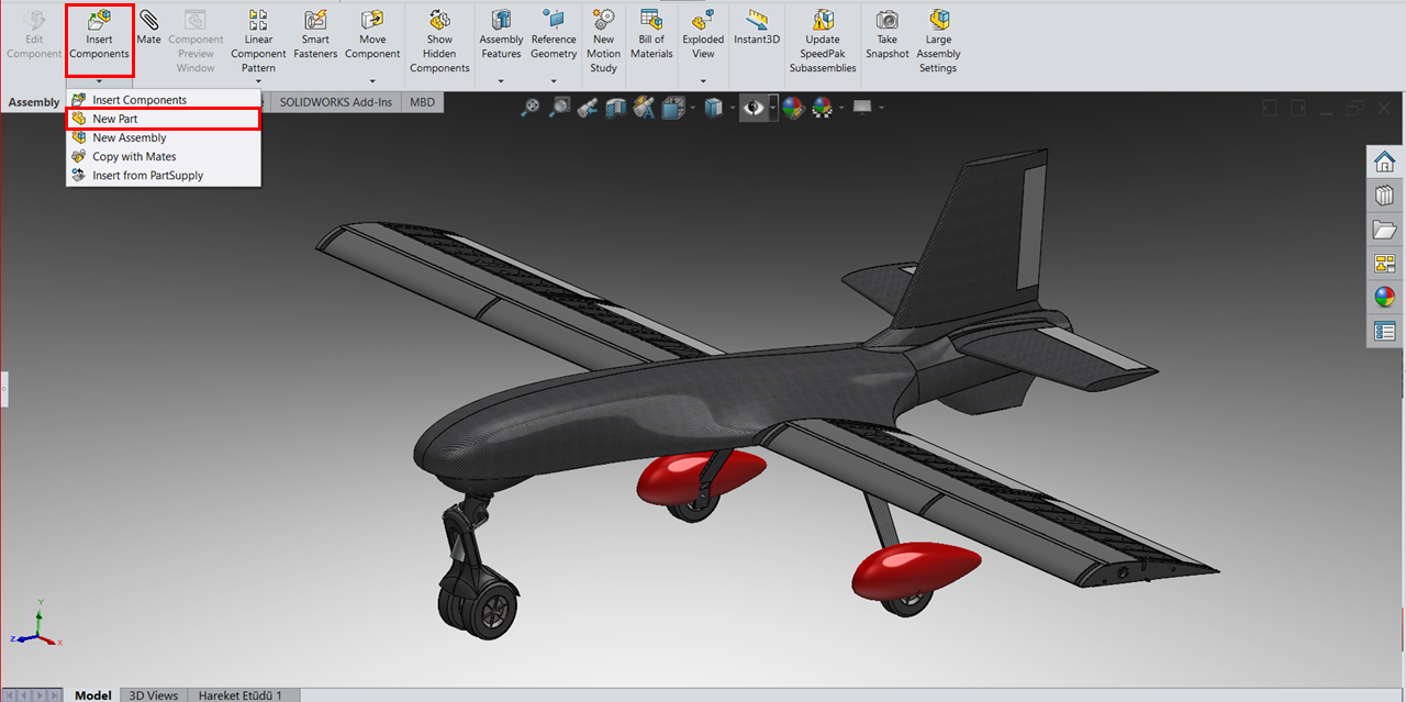
- Faster and More Efficient Workflow: Instead of creating separate part files with “estimated” dimensions, you can work directly within the assembly using the Insert Component > New Part command, resulting in a faster and more reliable design process.
Step 2: Plane Selection and Using References
After selecting the New Part command, SOLIDWORKS prompts you to choose a sketch plane. This is a critical decision. Rather than using standard planes (Front/Top/Right), you should select a surface of the reference component—such as the side surface of the wing profile—as your sketch plane.
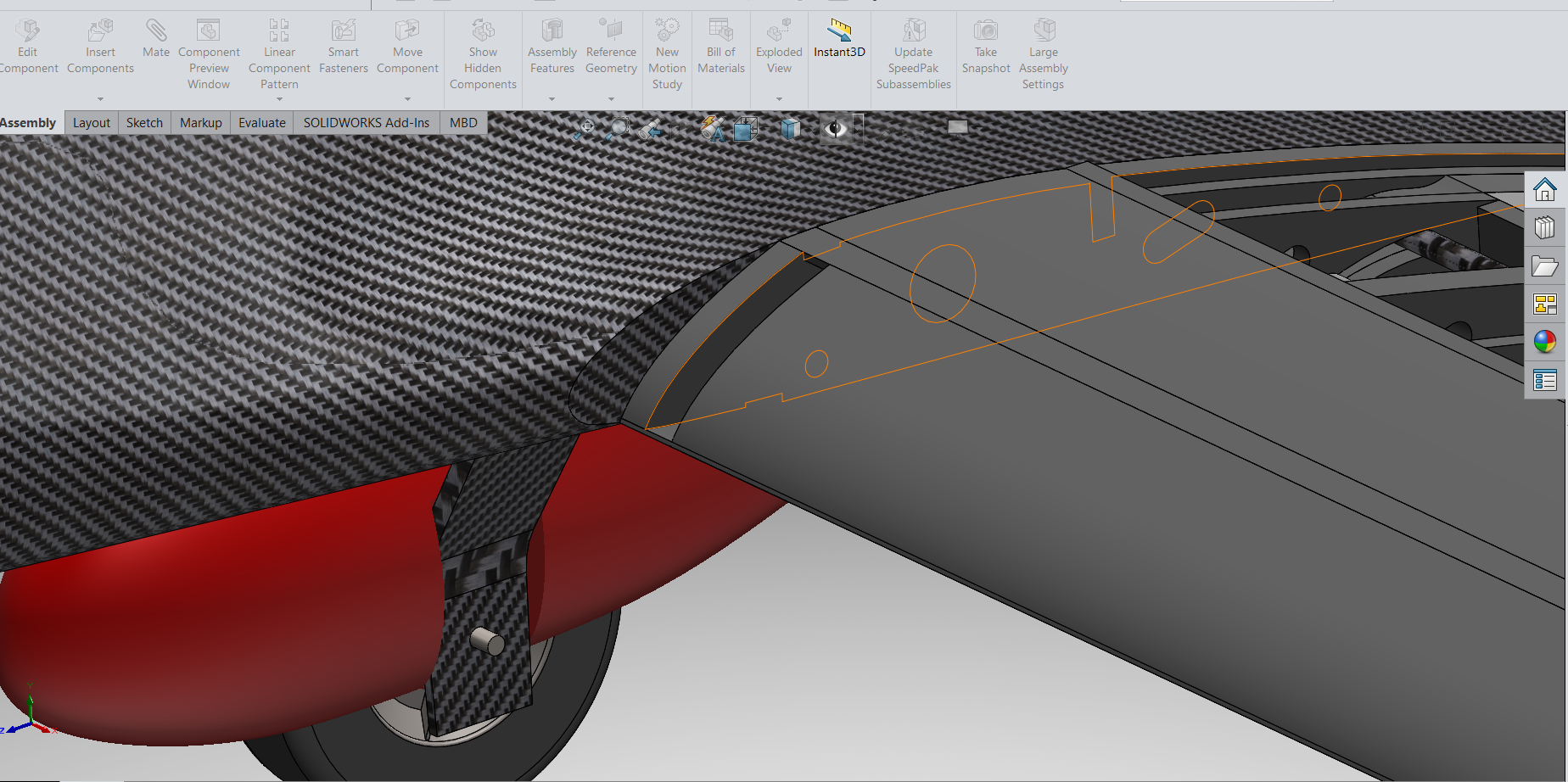
The Importance of the “Convert Entities” Command:
Once the sketch environment is active:
- There is no need to redraw slat rails or linkage paths from scratch.
-
Using the Convert Entities command, designers precisely transfer internal wing contours or trajectory curves from the master layout sketch directly into the active part as an exact copy.
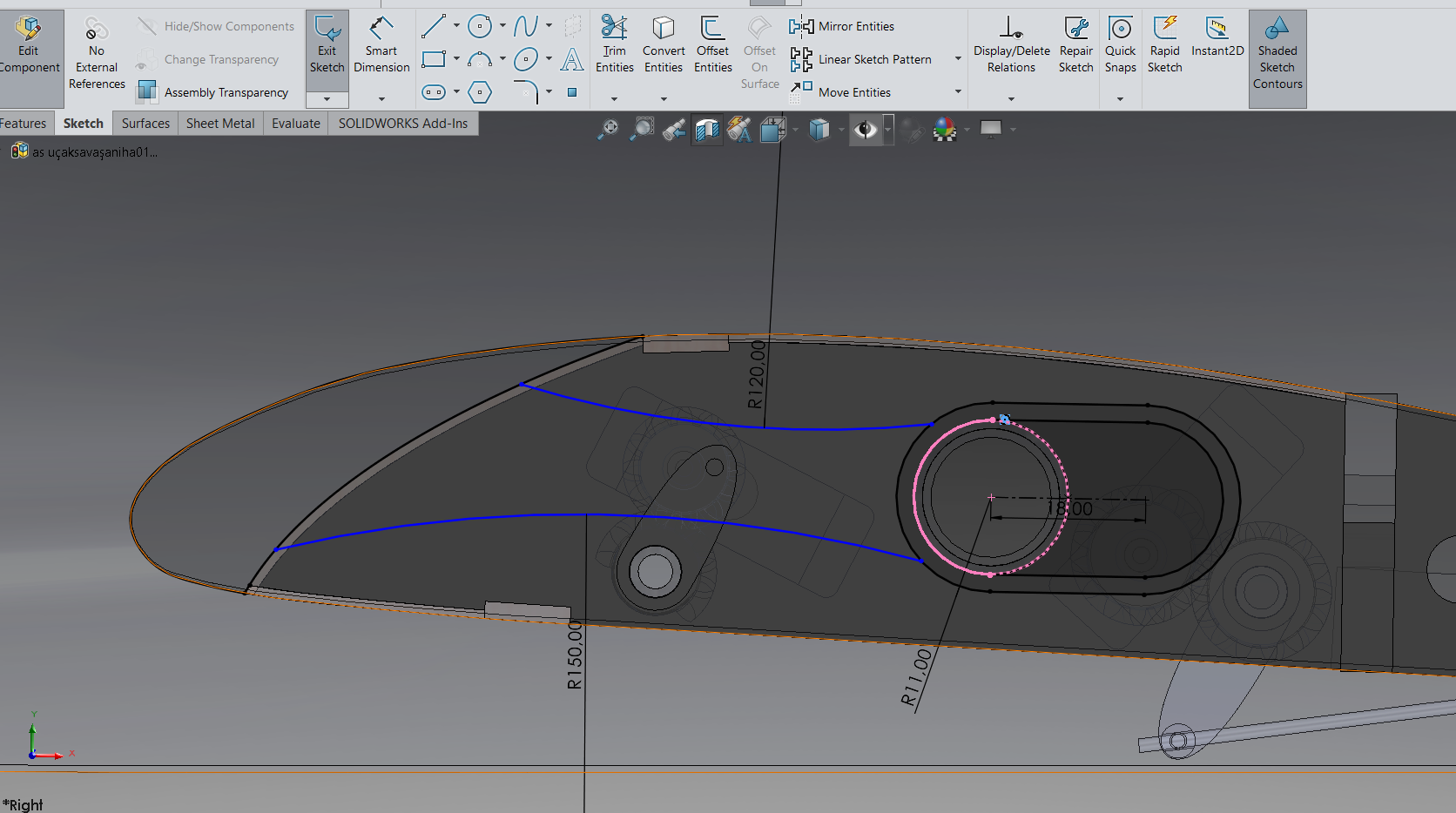
Using the Right References:
- Avoid Fixed Dimensions: Never manually dimension geometry that depends on the master design. For example, assigning a fixed value like “R9 mm” to a rail profile will cause the part to remain unchanged when the main geometry is updated—eventually breaking the assembly. Instead, allow these edges to remain linked using relations such as On Edge.
- Dimension Only What Remains Constant: Apply dimensions only to part specific features that should not change, such as the slat rail wall thickness (e.g., 3 mm).
Step 3: Adding Volume to the Geometry
Once the reference sketches are complete, the next step is to give the part its third dimension.

When using the Extruded Boss/Base command here, it is crucial to maintain a parametric approach. If the part fits between two surfaces, avoid using an arbitrary Blind extrusion.
Instead, select Up to Surface and reference the corresponding surface in the assembly.
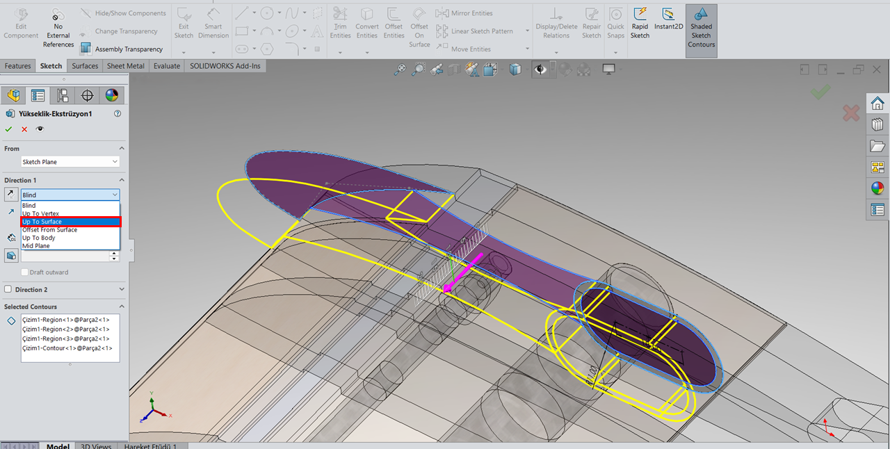
This ensures that whenever the distance between reference surfaces in the main design changes, the slat thickness updates automatically in real-time.

Step 4: Live Revision – Real-Time Part Updates
The most satisfying moment in this workflow is seeing the system respond correctly to change. The true strength of Top-Down Design lies not in moving the mechanism, but in modifying it.
 To validate the system, we returned to the Master Layout Sketch and introduced several changes:
- The position of the guide tube was modified.
- The location of the linkage arm was updated.
Step 5: Freezing the Design – Managing External References
The real-time update capability of Top-Down Design is invaluable during the design phase. However, once the design reaches production maturity, you may no longer want parts to change.
If you are concerned that future assembly modifications might affect finalized components, it is time to break these links:
- Right-click the part name at the top of the Feature Manager Design Tree.
- Navigate to External References.
- Click the Break All button.

This action freezes the geometry in its current state. Even if the wing profile is later modified, the slat component will remain unchanged as a fixed solid model. This step effectively transitions the design from a “live” state to a “locked” state and serves as a critical safeguard before manufacturing.

Conclusion
With this approach, we move beyond static CAD models and build a dynamic, responsive system that easily adapts to change. In engineering, the only constant is change itself. This workflow transforms revisions from a destructive process into a simple and manageable update.
When integrating a complex mechanism into a highly constrained volume, pause before creating individual parts. Start by designing directly within the assembly and Establish strong references and let the system work for you, not against you.

Mechanical Designer at BTU Uzay Havacılık ve Savunma Sanayii Topluluğu
Durmuş Uzer is a third-year Mechatronics Engineering student at Bursa Technical University with a strong interest in aviation. Since 2022, he has worked on UAV mechanical design, structural analysis, and composite manufacturing, and is the Mechanical Team Leader of the award-winning BTÜ-Poyraz Team, which won the Best Design Award at Savaşan İHA 2025.
Latest posts by Durmuş Uzer (see all)
- Slat Mechanisms Using Top-Down Modeling in SOLIDWORKS - 9 January 2026
Subscribe
0 Comments
Oldest
