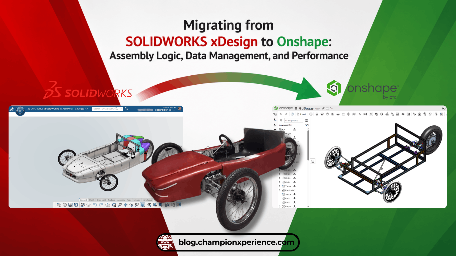
SOLIDWORKS xDesign to Onshape Migration is becoming increasingly common as more engineering teams adopt cloud-native CAD platforms. In this continuation of the series, we focus on the GoBuggy project, which we migrated from SOLIDWORKS xDesign to Onshape. In this article, we examine the Assembly, Data Management, and Performance differences between the two software environments.
Assembly Differences
This is precisely where a user transitioning from the SOLIDWORKS ecosystem (SOLIDWORKS Desktop or SOLIDWORKS xDesign) to the Onshape platform needs to adapt. While SOLIDWORKS features an assembly methodology that progresses by reducing degrees of freedom (DOF), Onshape utilizes a methodology where parts are connected via local coordinate systems. In the industry, the assembly method in SOLIDWORKS is called Constraint-Based Assembly, whereas the approach adopted by Onshape is commonly referred to as Kinematic Joint-Based Assembly. In Onshape’s own terminology, this method is specifically implemented through what are known as Mate connectors.
Constraint-Based Assembly (Low-Level)
Let’s explain this structure with a simple example: Suppose you need to fit a bolt into its seat. The initial degrees of freedom (DOF) of the bolt is 6. In SOLIDWORKS, you must first define a “Concentric” mate between the cylindrical surfaces, and then apply a “Coincident” mate between the surfaces where the bolt head will seat. At this point, the degrees of freedom of the bolt drops to 1. To prevent the bolt from spinning around its own axis within the seat, you can apply a “Coincident” mate between a reference plane intersecting the center of the bolt and a reference plane intersecting the center of the hole. In the final state, the degrees of freedom becomes 0. In its most basic form, the usage logic of SOLIDWORKS assembly commands works this way.
Kinematic Joint-Based Assembly (High-Level)
If we examine the same example on Onshape, using a single command is sufficient to fit the bolt into the seat. Thanks to the software’s kinematic joint logic, we can directly reduce the bolt’s degrees of freedom (DOF) to 0 using only one single command like the Fastened Mate. While adapting to this methodology requires a brief initial learning curve, consolidating multiple constraints into a single command minimizes repetitive steps, providing a faster and more streamlined assembly workflow once the logic is mastered.
Onshape Fastened Mate vs SOLIDWORKS xDesign Mate (Both videos have been sped up to 2x. )
Low-Level vs High-Level
Depending on the intended use, both platforms offer numerous assembly commands. Since we are examining a migration process, you can review which command corresponds to which, along with the differences between them, in the table below.
| Desired Motion / Connection Type |
Onshape Command (Clicked in Toolbar) |
SolidWorks xDesign Workflow (Applied UI / Popup Commands) |
xDesign Tree Result (Design Manager Constraint) |
| Fully Fixed (0 DOF)
(e.g., Bolt-Nut, Welded Parts) |
Fastened Mate
|
Coincident + Concentric + Lock Rotation (or intersecting planar coincidences) |
Rigid |
| Rotation Only (1 DOF)
(e.g., Hinge, Bearing, Wheel) |
Revolute Mate |
Concentric (Cylindrical faces) + Coincident (Mating end faces) |
Revolute |
| Linear Translation Only (1 DOF)
(e.g., Piston, Slider, Rail) |
Slider Mate |
Coincident (Face seating) + Parallel / Perpendicular (Orientation to prevent rotation) |
Prismatic |
| Rotation + Translation (2 DOF)
(e.g., Shock absorber shaft, Free shaft) |
Cylindrical Mate |
Only Concentric (Selecting coaxial cylindrical faces) |
Cylindrical |
| 3-Axis Spherical Rotation (3 DOF)
(e.g., Ball joint, Rod end) |
Ball Mate |
Concentric (Matching spherical faces or center points) |
Spherical |
| Planar Freedom (3 DOF)
(e.g., Cube sliding on a table) |
Planar Mate |
Only Coincident (Selecting two flat faces or planes) |
Planar |
| Curve / Surface Tracking
(e.g., Pin-Slot, Cam-Follower) |
Pin Slot / Tangent |
Coincident / Tangent (Point to curve/surface or tangent faces) |
Point Curve / Point Surface |
| Centering & Symmetric Alignment
(Centering a part between two faces) |
Width Mate |
Symmetry Constraint |
Symmetry |
Since we used general assembly mates in the GoBuggy project, I conducted the comparison accordingly. In this context, I did not include mechanical assembly mates in the table I prepared.
Mating Based on Reference Planes and Axes
You will also see that the two software use different technologies when you want to define a mate based on a specific reference. For example, let’s assume you need to assemble a rod between the tabs of a U-bracket, perfectly centered:
- SOLIDWORKS xDesign: After making the cylindrical surface of the rod and the cylindrical surface on the tab concentric, you define a coincident relationship between the center plane of the rod facing perpendicular to the hole and the center plane of the bracket. It is also optionally possible to define these relationships using the Distance or Symmetric commands.
- Onshape: In the same scenario, you can assign a smart coordinate system right in the middle of the tabs using the Mate Connector command (by selecting the “Between Entities” placement type). A Mate Connector is not just a simple coordinate system, it is a smart reference point that can be used for multiple purposes. After performing the same operation for the rod, you can complete the assembly in a single step in the assembly environment by selecting only these Mate Connectors with the Revolute Mate command.
Onshape Mate Connector vs SOLIDWORKS xDesign Mate (Both videos have been sped up to 2x. )
- Mate Connector Flexibility: In Onshape, the Mate Connector tool is also integrated into many other design commands. For example, instead of assigning a new plane to a part that lacks a mid-plane, you can facilitate your mirroring operations by placing a coordinate system right in the center of the part with a Mate Connector to act as a plane. Since it is integrated into the commands, you have the opportunity to create a Connector directly without exiting the Mirror command.
Adding Components to the Assembly
Aside from the workflow differences between assembly commands, we should also touch upon the methodological differences in adding components to the assembly environment:
- SOLIDWORKS xDesign: There are no separate windows for design and assembly processes, all operations are conducted over a single action bar. After creating a multi-body part design, you can convert each body into an assembly component that can move in space using the Make Component command, and then assemble them using mating tools. Additionally, just like in the SOLIDWORKS Desktop version, you can also perform assemblies by inserting each part independently.
- Onshape: Within the document structure, there are two distinct tabs: Part Studio (Design Environment) and Assembly (Assembly Environment), and the commands vary according to these workspaces. In Onshape, you can directly call independent parts into the assembly environment, or if you have a multi-part model designed in the Part Studio environment, you can also include each part separately into the assembly space.
Data Management Differences
SOLIDWORKS xDesign draws its PDM/PLM power from the ENOVIA infrastructure under the umbrella of the 3DEXPERIENCE platform. Onshape, on the other hand, comes out of the box with a modernized built-in PDM system. In addition to that, it can also work integrated with PLM systems through additional PTC software such as Arena PLM.
Data Saving and History Management
- SOLIDWORKS xDesign: Every save operation overwrites the relevant physical product file. When you create a new revision on a component, you essentially save a new Physical Product file into the Collaborative Space in a way that establishes a link between the data.
- Onshape: Every action is instantly recorded in the history, and there is no independent save button in the system. Since every single step taken is automatically stored in the History, it offers unlimited undo capabilities. The designer’s primary working environment and the place where the design always remains up to date is the “Main” branch. When a new document is created, the Main area is automatically generated within the History, and the user can always make edits here.
Version and Revision Distinction
One of the aspects where Onshape differentiates itself from SOLIDWORKS xDesign is the Version creation process. In Onshape, apart from Revision and Branch, there is also a “Version” creation process. When a version is created, it is as if a screenshot of the current state of the design is taken, and this state is preserved in the History area. When you want to view this created version, the system opens it with a Read-Only logic. In other words, you cannot make changes directly on it. Thanks to a version, the designer creates a safe checkpoint that protects the current state of their data.
The primary differences from a revision lie in both workflow and scope: A revision is tied to a corporate approval mechanism and applies specifically to the individual parts or assemblies selected for release, whereas a version is entirely under the designer’s own control and covers the entire document along with every element inside it.
Branch and Merge Processes
- SOLIDWORKS xDesign: When you create a new branch, another distinct physical product file is generated. Once the modifications made on the branch are completed, the features in the selected branch can be transferred to the latest revision using the “Merge” command. This merging feature was added to the software through recent updates, starting to offer a function similar to Onshape.
- Onshape: Since it operates on a document-centric rather than a file-based architecture, when you create a Version or a Branch, this operation involves all data within the document. Whichever branch holds the desired design data, that line is merged with Main, ensuring that the data remains in its most up-to-date form.
Lifecycle and Release Management
- SOLIDWORKS xDesign: No changes can be made to data that has been set to the “Released” state in the product lifecycle unless a new revision is created. Operations to be performed in product lifecycle control can be executed without an approval mechanism, however, since it is generally used in conjunction with Change Management applications in companies, it progresses subject to a specific approval.
- Onshape: Due to its design-focused structure, Release Management is characterized as a modern PDM tool rather than a PLM tool. Since a document can contain dozens of different parts and releasing all of them simultaneously could create issues in manufacturing processes, the “Release” operation is not document-based, it only affects the selected data and is subject to an approval mechanism. Revisions that can be made post-release also operate directly on a part-data basis rather than a document basis.
Compare Tools
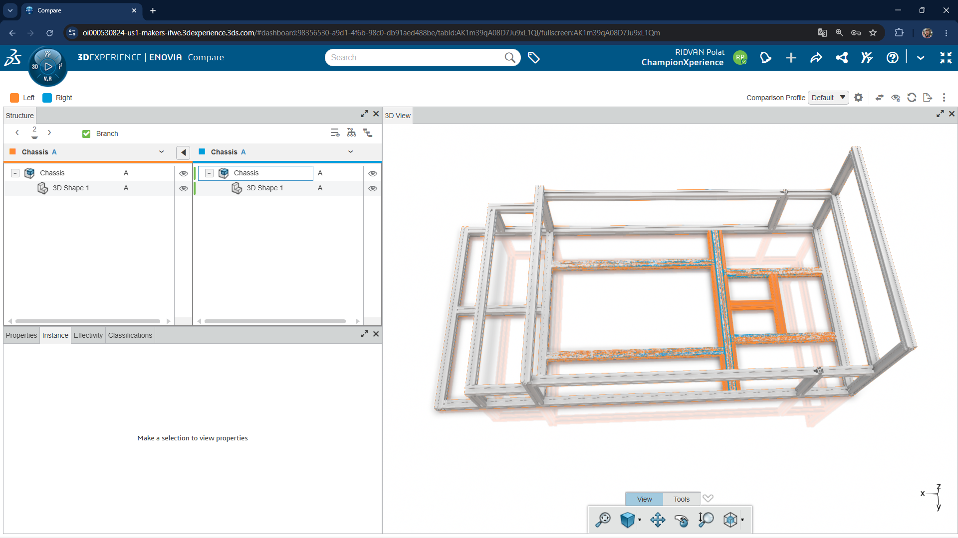
- SOLIDWORKS xDesign: Due to the software’s widget-based ecosystem, inspecting geometric and structural differences between two branches or revisions requires stepping out of the modeling environment (or switching between tabs if you are using a Dashboard) to open the ENOVIA Compare widget on the platform. The ENOVIA Compare widget displays the differences between branches or revisions. In addition to visually showing geometric changes with different colors, if you are comparing an assembly, it also displays the differences within the feature tree.
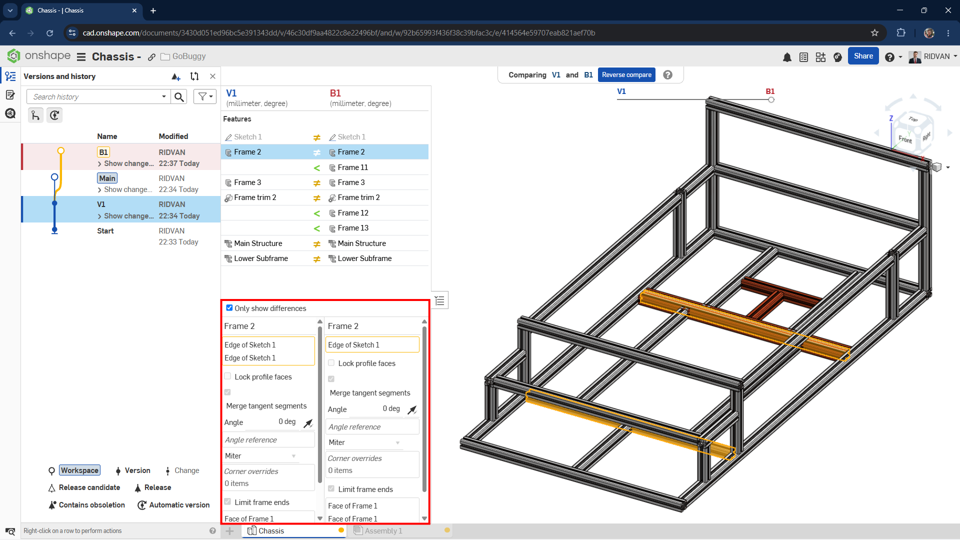
- Onshape: The version and branch comparison (Compare) feature comes natively built-in and integrated directly within the document history. While in the modeling environment, a designer can select any two branches or versions, and in addition to showing geometric modifications with color coding, it displays the differences between the commands in the Feature List and what was selected differently inside those commands (The area highlighted in red in the image below illustrates these differences within the command).
Performance and Mobile Compatibility
Both softwares run on a web browser, therefore, you must have an above-average, stable internet connection to achieve a smooth design experience and a workspace without latency.
Cloud Architectural Differences
- SOLIDWORKS xDesign: Although it operates through a web browser, it utilizes Dassault Systèmes’ geometric modeling kernel (CGM). It leverages the graphics card (GPU) power of local hardware and browser-based WebGL technology for rendering large data on the screen and performing graphic calculations.
- Onshape: To keep data transfer at a minimum level, it communicates between the client (browser) and cloud servers via short and intermittent command messages. In this way, it aims for stable operation even on low-end computers by minimizing hardware requirements.
Mobile Interface and Usage Dynamics
Both softwares demonstrate full compatibility with mobile devices. However, their methods of providing mobile integration diverge in terms of user experience:
- SOLIDWORKS xDesign: When the “Touch Mode” option located in the interface is activated, command icons automatically enlarge to facilitate stylus or finger usage, a special shortcut bar that simplifies selection is placed at the edge of the screen, and ergonomic features such as “Rotate Lock”, which prevents accidental rotation of the model, come into play. Additionally, ready-to-use and resizable 3D models such as Cube, Cylinder, Sphere, and Torus enhance the mobile experience by reducing the need for sketching commands. It suggests usable commands based on touches made on the sketch or model. SOLIDWORKS xDesign does not differentiate or react according to the difference between a stylus and a finger.
- Onshape: It offers full access via mobile device browsers, and also features a native Mobile App optimized for iOS and Android operating systems. To maximize screen area, this application includes specialized tools that focus solely on part design, sketch, and assembly environments. Multi-finger movements (Gestures) are integrated to facilitate touch usage. For instance, it offers smart shortcuts such as single-finger rotation, two-finger pan, and executing the right-click (Context Menu) function of a mouse when touching the screen with two fingers simultaneously. Furthermore, it includes a precision selection tool (Position Selector) that magnifies the area under your finger so you can make precise selections on complex geometries.
With its latest updates, Onshape has also brought touch-specific features to browser usage. For example, when you want to use Onshape via a browser on your tablet, it can recognize the difference between using a stylus and a finger, reacting accordingly.
Performance
It may not be accurate to make a direct, sharp argument regarding performance. Both software need to be tested objectively under specific parameters such as large assemblies and part counts. However, in general usage, as someone who has personally tested the GoBuggy project on both software, I can say that Onshape offers a more optimized, fast-loading, and stable operation without stuttering.
Ready to Start Your Onshape Journey?
Thinking about switching to Onshape but don’t know where to start? We have great news for you. If you haven’t experienced PTC’s cloud-native CAD and PDM platform yet, you can click on the link below to create a free account. Even better, you can try Onshape Professional—including tools like Simulation and Render Studio—free for 6 months.
6 Months Free Access to Onshape Professional
Ridvan Polat is a SOLIDWORKS Elite Application Engineer, Founder of ChampionXperience, and a recognized SOLIDWORKS, ENOVIA, and 3DEXPERIENCE Champion. He specializes in CATIA & ENOVIA technical support and 3DEXPERIENCE early engagement adaptation, helping organizations optimize PLM workflows.
Latest posts by Rıdvan Polat
(see all)


